

Step
1540-1
1.
Ensure
that
the
diagnostics
and
the
operating
system
are
shut
down.
2.
Turn
off
the
power.
3.
Select
slow
boot
mode
(select
disable
fast
boot)
on
the
System
Power
Control
menu
from
the
service
processor
main
menu.
4.
Turn
on
the
power
to
boot
standalone
diagnostics
from
CD.
5.
Insert
the
diagnostic
CD-ROM
into
the
CD-ROM
drive.
Does
the
CD-ROM
appear
to
operate
correctly?
NO
Go
to
“Boot
Problems
and
Concerns”
on
page
155.
YES
Go
to
“Step
1540-2.”
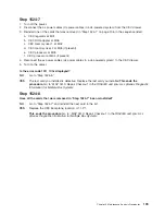
Step
1540-2
1.
When
the
keyboard
indicator
is
displayed
(the
word
keyboard
),
press
the
5
key
on
the
system
console.
2.
Enter
the
appropriate
password
when
you
are
prompted
to
do
so.
Is
the
Please
define
the
System
Console
screen
displayed?
NO
Go
to
“Step
1540-3.”
YES
Go
to
“Step
1540-12”
on
page
117.
Step
1540-3
The
system
is
unable
to
boot
standalone
diagnostics.
Check
the
service
processor
error
log
and
the
primary
I/O
drawer
operator
panel
for
additional
error
codes
resulting
from
the
slow
boot
in
“Step
1540-1.”
Did
the
slow
boot
generate
a
different
error
code
from
the
one
that
originally
sent
you
to
MAP
1540?
YES
Restore
fast
boot
mode
(select
enable
fast
boot)
on
the
System
Power
Control
menu
from
the
service
processor
main
menu.
Go
to
“Checkpoint
and
Error
Code
Index”
on
page
161
and
follow
the
actions
for
the
new
error
code.
NO
Continue
“Step
1540-3”
below.
The
boot
attempts
that
follow
will
attempt
to
get
the
Please
define
the
System
Console
prompt
on
the
system
console.
Ignore
any
codes
that
may
appear
on
the
operator
panel
unless
stated
otherwise.
Chapter
3.
Maintenance
Analysis
Procedures
111
Summary of Contents for RS/6000 Enterprise Server M80
Page 1: ...RS 6000 Enterprise Server Model M80 Eserver pSeries 660 Model 6M1 Service Guide SA38 0571 01...
Page 10: ...x Service Guide...
Page 14: ...xiv Service Guide...
Page 16: ...xvi Service Guide...
Page 22: ...Data Flow 4 Service Guide...
Page 30: ...CEC Card Cage Rear of CEC drawer viewed from top cover removed 12 Service Guide...
Page 84: ...66 Service Guide...
Page 176: ...158 Service Guide...
Page 376: ...358 Service Guide...
Page 430: ...412 Service Guide...
Page 485: ...Chapter 11 Parts Information This chapter contains parts information for the system 467...
Page 486: ...CEC Drawer Card Assembly 9 468 Service Guide...
Page 488: ...CEC Drawer Backplane 5 2a 1 2 3 4 470 Service Guide...
Page 490: ...CEC Drawer Power Supplies 1 2 3 4 5 6 7 8 9 472 Service Guide...
Page 492: ...CEC Drawer Fan Assemblies 2 1 3 4 5 6 8 9 10 11 12 13 7 14 474 Service Guide...
Page 496: ...7 8 9 10 6 1 2 3 4 4 5 478 Service Guide...
Page 508: ...490 Service Guide...
Page 520: ...502 Service Guide...
Page 522: ...504 Service Guide...
Page 526: ...508 Service Guide...
Page 558: ...540 Service Guide...
Page 565: ......


