


Chapter
1.
Reference
Information
This
chapter
provides
an
overview
of
the
system,
including
a
logical
description
and
a
physical
overview.
Additional
details
pertaining
to
the
system
are
also
provided,
as
follows:
v
Memory
overview
and
placement
v
General
description
of
the
operator
panel
v
Cabling
rules
v
System
location
rules
and
descriptions
v
Powering
on
and
off
the
system
v
Power
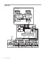
flow
v
Data
flow
Overview
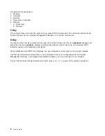
The
RS/6000
Enterprise
Server
Model
M80
and
Eserver
pSeries
660
Model
6M1
systems
are
multiprocessor,
multibus
systems
packaged
in
two
to
five
drawers.
The
processors
and
memory
are
packaged
in
an
8
EIA-unit
central
electronics
complex
(CEC)
drawer,
and
the
optional
DASD
and
I/O
devices
are
in
5
EIA-unit
I/O
drawers.
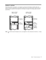
The
basic
system
consists
of
one
CEC
drawer
and
one
I/O
drawer
in
the
same
rack.
You
can
expand
the
system
by
adding
up
to
three
additional
I/O
drawers
in
a
minimum
of
two
racks.
A
number
of
cables
connect
the
CEC
and
I/O
drawers.
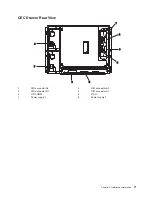
These
cables
include:
v
SPCN
(System
Power
Control
Network)
cables
v
V/S
COMM
cables
v
RIO
(Remote
Input
Output)
cables
v
JTAG
cable
An
ac
power
cord
(dc
power
cord
in
a
dc-powered
system)
is
connected
to
the
CEC
drawer
(drawer
1),
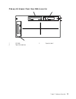
primary
I/O
drawer
(drawer
0),
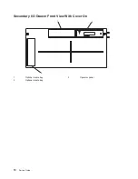
and
secondary
I/O
drawer
(drawer
2).
You
can
also
connect
two
additional
secondary
drawers
(drawers
3
and
4)
in
another
rack
with
a
separate
power
distribution
unit
and
ac
power
cord
(dc
power
cord
in
a
dc-powered
system).
A
dc-powered
system
has
no
power
distribution
unit.
1
Summary of Contents for RS/6000 Enterprise Server M80
Page 1: ...RS 6000 Enterprise Server Model M80 Eserver pSeries 660 Model 6M1 Service Guide SA38 0571 01...
Page 10: ...x Service Guide...
Page 14: ...xiv Service Guide...
Page 16: ...xvi Service Guide...
Page 22: ...Data Flow 4 Service Guide...
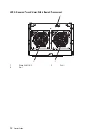
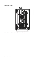
Page 30: ...CEC Card Cage Rear of CEC drawer viewed from top cover removed 12 Service Guide...
Page 84: ...66 Service Guide...
Page 176: ...158 Service Guide...
Page 376: ...358 Service Guide...
Page 430: ...412 Service Guide...
Page 485: ...Chapter 11 Parts Information This chapter contains parts information for the system 467...
Page 486: ...CEC Drawer Card Assembly 9 468 Service Guide...
Page 488: ...CEC Drawer Backplane 5 2a 1 2 3 4 470 Service Guide...
Page 490: ...CEC Drawer Power Supplies 1 2 3 4 5 6 7 8 9 472 Service Guide...
Page 492: ...CEC Drawer Fan Assemblies 2 1 3 4 5 6 8 9 10 11 12 13 7 14 474 Service Guide...
Page 496: ...7 8 9 10 6 1 2 3 4 4 5 478 Service Guide...
Page 508: ...490 Service Guide...
Page 520: ...502 Service Guide...
Page 522: ...504 Service Guide...
Page 526: ...508 Service Guide...
Page 558: ...540 Service Guide...
Page 565: ......


