
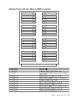


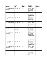
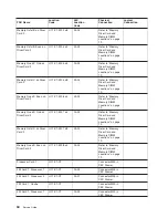

Location
Code
Memory
DIMMs
U1.1-P1-M1.5
x8
Memory
Octal
C
(DIMMs
5,
6,
13,
14,
21,
22,
29,
30)
U1.1-P1-M1.6
x4
Memory
Quad
C
Even
(DIMMs
6,
14,
22,
30)
U1.1-P1-M1.7
x4
Memory
Quad
D
Odd
(DIMMs
7,
15,
23,
31)
U1.1-P1-M1.7
x8
Memory
Octal
D
(DIMMs
7,
8,
15,
16,
23,
24,
31,
32)
U1.1-P1-M1.8
x4
Memory
Quad
D
Even
(DIMMs
8,
16,
24,
32)
U1.1-P1-M2.n
Individual
Memory
DIMMs
on
Riser
Card
2
(n
denotes
DIMM
number)
U1.1-P1-M2.1
x4
Memory
Quad
A
Odd
(DIMMs
1,
9,
17,
25)
U1.1-P1-M2.1
x8
Memory
Octal
A
(DIMMs
1,
2,
9,
10,
17,
18,
25,
26)
U1.1-P1-M2.1
x32
All
Memory
DIMMs
on
Riser
Card
2
U1.1-P1-M2.2
x4
Memory
Quad
A
Even
(DIMMs
2,
10,
18,
26)
U1.1-P1-M2.3
x4
Memory
Quad
B
Odd
(DIMMs
3,
11,
19,
27)
U1.1-P1-M2.3
x8
Memory
Octal
B
(DIMMs
3,
4,
11,
12,
19,
20,
27,
28)
U1.1-P1-M2.4
x4
Memory
Quad
B
Even
(DIMMs
4,
12,
20,
28)
U1.1-P1-M2.5
x4
Memory
Quad
C
Odd
(DIMMs
5,
13,
21,
29)
U1.1-P1-M2.5
x8
Memory
Octal
C
(DIMMs
5,
6,
13,
14,
21,
22,
29,
30)
U1.1-P1-M2.6
x4
Memory
Quad
C
Even
(DIMMs
6,
14,
22,
30)
U1.1-P1-M2.7
x4
Memory
Quad
D
Odd
(DIMMs
7,
15,
23,
31)
U1.1-P1-M2.7
x8
Memory
Octal
D
(DIMMs
7,
8,
15,
16,
23,
24,
31,
32)
U1.1-P1-M2.8
x4
Memory
Quad
D
Even
(DIMMs
8,
16,
24,
32)
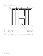
For
physical
locations,
see
“Memory
Riser
Card
and
Memory
DIMM
Locations”
on
page
19.
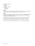
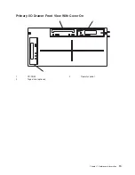
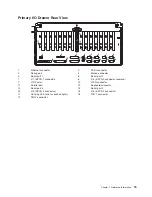
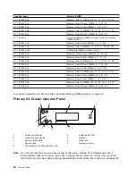
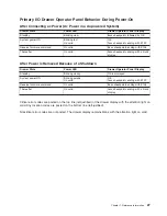
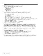
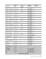
Primary
I/O
Drawer
Operator
Panel
R
1
2
8
9
5
3
7
4
6
!
1
Power
on/off
button
2
Power
on/off
LED
3
Operator
panel
display
4
Speaker
5
Serial
number
plate
6
Reset
icon
7
Reset
button
8
Service
use
only
9
Disturbance
or
system
attention
LED
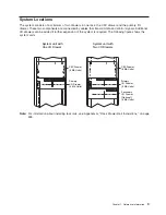
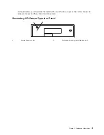
Note:
You
must
activate
the
service
processor
reset
button
very
carefully.
An
insulated
paper
clip
is
recommended.
Unbend
the
clip
so
that
it
has
a
straight
section
about
two
inches
long.
Insert
the
clip
straight
into
the
hole,
keeping
the
clip
perpendicular
to
the
plastic
bezel.
When
you
engage
the
20
Service
Guide
Summary of Contents for RS/6000 Enterprise Server M80
Page 1: ...RS 6000 Enterprise Server Model M80 Eserver pSeries 660 Model 6M1 Service Guide SA38 0571 01...
Page 10: ...x Service Guide...
Page 14: ...xiv Service Guide...
Page 16: ...xvi Service Guide...
Page 22: ...Data Flow 4 Service Guide...
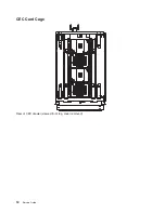
Page 30: ...CEC Card Cage Rear of CEC drawer viewed from top cover removed 12 Service Guide...
Page 84: ...66 Service Guide...
Page 176: ...158 Service Guide...
Page 376: ...358 Service Guide...
Page 430: ...412 Service Guide...
Page 485: ...Chapter 11 Parts Information This chapter contains parts information for the system 467...
Page 486: ...CEC Drawer Card Assembly 9 468 Service Guide...
Page 488: ...CEC Drawer Backplane 5 2a 1 2 3 4 470 Service Guide...
Page 490: ...CEC Drawer Power Supplies 1 2 3 4 5 6 7 8 9 472 Service Guide...
Page 492: ...CEC Drawer Fan Assemblies 2 1 3 4 5 6 8 9 10 11 12 13 7 14 474 Service Guide...
Page 496: ...7 8 9 10 6 1 2 3 4 4 5 478 Service Guide...
Page 508: ...490 Service Guide...
Page 520: ...502 Service Guide...
Page 522: ...504 Service Guide...
Page 526: ...508 Service Guide...
Page 558: ...540 Service Guide...
Page 565: ......


