


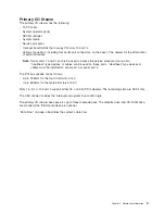
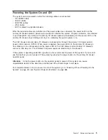


Powering
the
System
On
and
Off
The
system
can
be
powered
on
after
the
following
cables
are
connected:
v
V/S
COMM
Cable
v
All
RIO
cables
v
All
SPCN
cables
v
JTAG
Cable
v
All
PCI
cables
to
supported
drawers
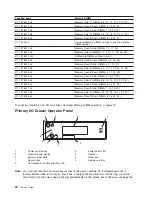
After
the
required
cables
are
installed,
and
the
power
cables
are
connected,
the
power
button
on
the
primary
I/O
drawer
operator
panel
can
be
pushed
to
initialize
the
system.
Progress
indicators,
also
referred
to
as
checkpoints
,
are
visible
on
the
primary
I/O
drawer
operator
panel
display
and
the
power
LED
on
the
primary
I/O
drawer
stops
blinking
and
stays
on,
indicating
the
system
power
is
on.
The
CEC
drawer
and
secondary
I/O
drawers
are
powered
on
through
the
primary
I/O
drawer
system
power
control
network
(SPCN).
When
power
is
applied,
the
power
LEDs
on
the
primary
I/O
drawer
go
from
blinking
to
on
continuously,
and
the
power
LED
on
the
CEC
drawer
and
secondary
I/O
drawer(s)
comes
on
and
stays
on.
This
indicates
that
power
levels
are
satisfactory
in
the
drawers.
If
the
system
is
operating
under
AIX,
type
the
shutdown
command
to
power
off
the
system.
If
you
cannot
use
this
method,
you
can
power
off
the
system
by
pressing
the
power
button
on
the
primary
I/O
drawer
operator
panel.
Attention:
Using
the
power
button
on
the
operator
panel
to
power
off
the
system
can
cause
unpredictable
results
in
the
data
files,
and
the
next
IPL
will
take
longer
to
complete.
For
complete
details
on
how
to
power
on
and
off
the
system,
go
to
“Powering
Off
and
Powering
On
the
System”
on
page
415
and
“System
Power-On
Methods”
on
page
386.
Chapter
1.
Reference
Information
5
Summary of Contents for RS/6000 Enterprise Server M80
Page 1: ...RS 6000 Enterprise Server Model M80 Eserver pSeries 660 Model 6M1 Service Guide SA38 0571 01...
Page 10: ...x Service Guide...
Page 14: ...xiv Service Guide...
Page 16: ...xvi Service Guide...
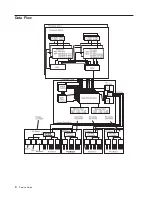
Page 22: ...Data Flow 4 Service Guide...
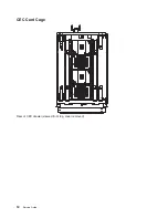
Page 30: ...CEC Card Cage Rear of CEC drawer viewed from top cover removed 12 Service Guide...
Page 84: ...66 Service Guide...
Page 176: ...158 Service Guide...
Page 376: ...358 Service Guide...
Page 430: ...412 Service Guide...
Page 485: ...Chapter 11 Parts Information This chapter contains parts information for the system 467...
Page 486: ...CEC Drawer Card Assembly 9 468 Service Guide...
Page 488: ...CEC Drawer Backplane 5 2a 1 2 3 4 470 Service Guide...
Page 490: ...CEC Drawer Power Supplies 1 2 3 4 5 6 7 8 9 472 Service Guide...
Page 492: ...CEC Drawer Fan Assemblies 2 1 3 4 5 6 8 9 10 11 12 13 7 14 474 Service Guide...
Page 496: ...7 8 9 10 6 1 2 3 4 4 5 478 Service Guide...
Page 508: ...490 Service Guide...
Page 520: ...502 Service Guide...
Page 522: ...504 Service Guide...
Page 526: ...508 Service Guide...
Page 558: ...540 Service Guide...
Page 565: ......


