


Installing
a
Hot-Pluggable
PCI
Adapter
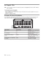
To
install
an
adapter,
do
the
following:
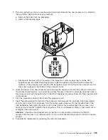
1.
Place
the
I/O
drawer
in
the
rear
service
position:
a.
If
you
have
not
already
done
so,
open
the
front
door
of
the
rack
unit.
b.
Loosen
the
two
thumbscrews
that
attach
the
front
bezel
to
the
drawer.
c.
Grasp
both
sides
of
the
front
bezel
and
pull
the
bezel
off
the
drawer.
d.
If
you
have
not
already
done
so,
open
the
rear
door
of
the
rack
unit.
e.
If
present,
remove
the
two
retaining
screws
at
the
rear
of
the
drawer.
Refer
to
“Rear
Service
Position”
on
page
463.
f.
Ensure
that
the
cables
do
not
restrain
drawer
movement.
g.
Grasp
the
bar
at
the
rear
of
the
drawer,
and
pull
the
drawer
to
the
rear
until
it
is
stopped
by
the
detents.
2.
Remove
the
two
thumbscrews
and
remove
the
top
cover
from
the
drawer.
3.
Refer
to
“PCI
Hot-Plug
Manager
Access”
on
page
423
and
follow
the
steps
in
the
access
procedure
to
select
PCI
Hot
Plug
Manager
.
Then
return
here
to
continue.
4.
From
the
PCI
Hot-Plug
Manager
menu,
select
Add
a
PCI
Hot-Plug
Adapter
and
press
Enter.
The
Add
a
Hot-Plug
Adapter
window
displays.
5.
For
adapter
placement
information,
see
the
PCI
Adapter
Placement
Reference
,
order
number
SA38-0538.
Then
select
an
empty
PCI
slot
for
the
adapter.
6.
Select
the
appropriate
empty
PCI
slot
from
the
ones
listed
on
the
screen,
and
press
Enter.
7.
Turn
the
locking
latch,
lift
the
plastic
stop,
and
remove
the
blank
cover.
8.
Follow
the
instructions
on
the
screen
to
install
the
adapter
until
the
visual
indicator
(LED)
for
the
specified
PCI
slot
is
set
to
the
Action
state.
See
“I/O
Drawer
PCI
Slot
LED
Definitions”
on
page
416.
9.
When
you
are
instructed
to
install
the
adapter
in
the
adapter
slot,
carefully
grasp
the
adapter
by
the
edges
and
align
the
adapter
in
the
slot
guides.
Insert
the
adapter
fully
into
the
adapter
slot
connector.
If
you
are
installing
a
full-length
adapter,
ensure
that
both
ends
of
the
adapter
engage
the
card
guides.
10.
Lower
the
plastic
stop
over
the
adapter
bracket
and
rotate
the
locking
latch
clockwise
until
it
clicks
into
the
locked
position.
Some
full-length
cards
can
be
supported
by
rotating
the
blue
adapter
latch
on
the
right
end
of
the
adapter
counterclockwise.
11.
Connect
appropriate
cables
and
devices
to
the
adapter.
12.
Continue
to
follow
the
screen
instructions
until
you
receive
a
message
that
the
installation
is
successful.
Successful
installation
is
indicated
by
the
OK
message
displayed
next
to
the
Command
field
at
the
top
of
the
screen.
13.
Press
the
F3
key
to
return
to
the
PCI
Hot-Plug
Manager
menu.
14.
Select
Install/Configure
Devices
Added
After
IPL
and
press
Enter.
Then
follow
the
instructions
on
the
screen.
Successful
installation
is
indicated
by
the
OK
message
displayed
next
to
the
Command
field
at
the
top
of
the
screen.
15.
If
you
do
not
have
other
adapters
to
install,
continue
with
the
next
step.
OR
If
you
have
other
adapters
to
install,
press
the
F3
key
to
return
to
the
PCI
Hot-Plug
Manager
menu
and
then
return
to
step
4.
16.
Press
F10
to
exit
the
Hot-Plug
Manager.
If
you
have
added,
removed,
or
replaced
any
adapters,
run
the
diag
-a
command.
If
the
system
responds
with
a
menu
or
prompt,
follow
the
instructions
to
complete
the
device
configuration.
17.
Replace
the
system
unit
covers
and
return
the
drawer
to
the
normal
operating
position.
422
Service
Guide
Summary of Contents for RS/6000 Enterprise Server M80
Page 1: ...RS 6000 Enterprise Server Model M80 Eserver pSeries 660 Model 6M1 Service Guide SA38 0571 01...
Page 10: ...x Service Guide...
Page 14: ...xiv Service Guide...
Page 16: ...xvi Service Guide...
Page 22: ...Data Flow 4 Service Guide...
Page 30: ...CEC Card Cage Rear of CEC drawer viewed from top cover removed 12 Service Guide...
Page 84: ...66 Service Guide...
Page 176: ...158 Service Guide...
Page 376: ...358 Service Guide...
Page 430: ...412 Service Guide...
Page 485: ...Chapter 11 Parts Information This chapter contains parts information for the system 467...
Page 486: ...CEC Drawer Card Assembly 9 468 Service Guide...
Page 488: ...CEC Drawer Backplane 5 2a 1 2 3 4 470 Service Guide...
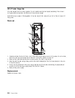
Page 490: ...CEC Drawer Power Supplies 1 2 3 4 5 6 7 8 9 472 Service Guide...
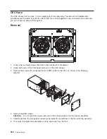
Page 492: ...CEC Drawer Fan Assemblies 2 1 3 4 5 6 8 9 10 11 12 13 7 14 474 Service Guide...
Page 496: ...7 8 9 10 6 1 2 3 4 4 5 478 Service Guide...
Page 508: ...490 Service Guide...
Page 520: ...502 Service Guide...
Page 522: ...504 Service Guide...
Page 526: ...508 Service Guide...
Page 558: ...540 Service Guide...
Page 565: ......


