
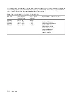
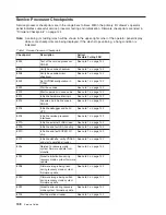
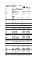


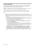
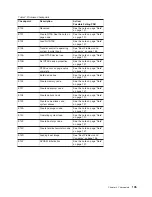


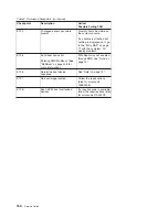
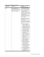
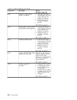
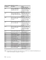


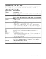


Table
2.
Firmware
Checkpoints
(continued)
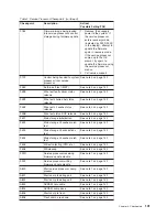
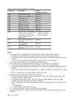
Checkpoint
Description
Action/
Possible
Failing
FRU
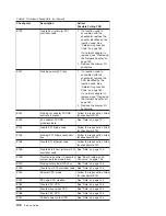
E1DC
Dynamic
console
selection.
If
a
console
is
attached
but
nothing
is
displayed
on
it,
follow
the
steps
associated
with
″
All
display
problems
″
in
the
Entry
MAP.
If
selection
screen(s)
can
be
seen
on
the
terminals
and
the
appropriate
key
on
the
input
device
associated
with
the
desired
display
or
terminal
is
pressed,
within
60
seconds,
but
there
is
no
response
to
the
keystroke:
v
If
selecting
the
console
with
a
keyboard
attached
to
the
system,
replace
the
keyboard.
If
replacing
the
keyboard
does
not
fix
the
problem,
replace
the
primary
I/O
backplane.
v
If
selecting
the
console
with
an
ASCII
terminal,
suspect
the
ASCII
terminal.
Use
the
problem
determination
procedures
for
the
terminal.
Replace
the
primary
I/O
backplane
if
these
procedures
do
not
reveal
a
problem.
Note:
Terminal
settings
should
be
set
to:
–
9600
Baud
–
No
Parity
–
8
Data
bits
–
1
Stop
bit
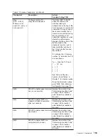
E1DE
Alternating
pattern
of
E1DE
and
E1AD
is
used
to
indicate
a
Default
Catch
condition
before
the
firmware
″
checkpoint
″
word
is
available.
See
“Note”
on
page
137.
E1DF
Create
diskette
drive
(disk)
node
See
“Note”
on
page
137.
E1F0
Start
O.B.E.
See
“Note”
on
page
137.
E1F1
Begin
selftest
sequence
on
boot
device(s).
Begin
SMS.
See
“Note”
on
page
137.
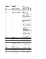
E1F2
Power-on
password
prompt.
Prompt
should
be
visible
on
the
system
console.
If
a
console
is
attached
but
nothing
is
displayed
on
it,
go
to
the
“Entry
MAP”
on
page
71
with
the
symptom
″
All
display
problems.
″
Chapter
4.
Checkpoints
149
Summary of Contents for RS/6000 Enterprise Server M80
Page 1: ...RS 6000 Enterprise Server Model M80 Eserver pSeries 660 Model 6M1 Service Guide SA38 0571 01...
Page 10: ...x Service Guide...
Page 14: ...xiv Service Guide...
Page 16: ...xvi Service Guide...
Page 22: ...Data Flow 4 Service Guide...
Page 30: ...CEC Card Cage Rear of CEC drawer viewed from top cover removed 12 Service Guide...
Page 84: ...66 Service Guide...
Page 176: ...158 Service Guide...
Page 376: ...358 Service Guide...
Page 430: ...412 Service Guide...
Page 485: ...Chapter 11 Parts Information This chapter contains parts information for the system 467...
Page 486: ...CEC Drawer Card Assembly 9 468 Service Guide...
Page 488: ...CEC Drawer Backplane 5 2a 1 2 3 4 470 Service Guide...
Page 490: ...CEC Drawer Power Supplies 1 2 3 4 5 6 7 8 9 472 Service Guide...
Page 492: ...CEC Drawer Fan Assemblies 2 1 3 4 5 6 8 9 10 11 12 13 7 14 474 Service Guide...
Page 496: ...7 8 9 10 6 1 2 3 4 4 5 478 Service Guide...
Page 508: ...490 Service Guide...
Page 520: ...502 Service Guide...
Page 522: ...504 Service Guide...
Page 526: ...508 Service Guide...
Page 558: ...540 Service Guide...
Page 565: ......