BF135A•BF150A
5-57
7. TROUBLESHOOTING WITHOUT
HDS TESTER
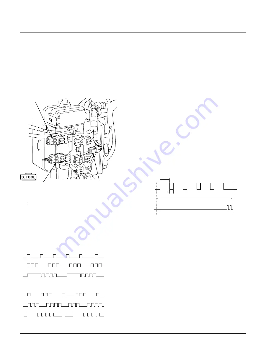
• Check of Number of Blinks of MIL
1. Remove the engine cover and the electric part cover
2. Disconnect the red 4P connector and connect (short-
circuit) the SCS short connector to the DLC (Data Link
Connector).
3. Check the number of blinks of the MIL.
Count the number of blinks when the MIL starts blink-
ing. The diagnostic trouble code (DTC) is indicated
repeatedly. The number of long blinks equals the first
digit and the number of short blinks equals the sec-
ond digit of the DTC.
When multiple problems occur simultaneously, the
MIL repeatedly indicates them by blinking separate
codes, one after another.
• ECM Reset Procedure
1. Turn the ignition switch OFF.
2. Short-circuit the 4P (Red) data link connector located
inside the electric part cover using the special tool
(SCS short connector).
3. Turn the ignition switch ON.
4. Turn the emergency stop switch ON (push) and OFF
(release). Repeat this procedure five times. (Repeat
turning the switch ON for 0.5 sec. or more and turning
it OFF for 0.1 sec. or more.)
5. Check that the buzzer sounds twice.
• The MIL should stay ON.
6. Turn the ignition switch OFF. (ECM reset procedure
completes.)
• Perform the step 4 through the step 6 within 20 sec-
onds.
4P CONNECTOR
(RED)
SCS SHORT CONNECTOR
070PZ-ZY30100
Separate problems:
Multiple problems:
See DTC 1.
See DTC 3.
See DTC 14.
See DTC 1
and 3.
See DTC 3
and 4.
See DTC 1
and 14
0.5 sec. or more
0.1 sec. or more
Within 20 sec.
BUZZER
ON
(Push)
OFF
(Release)
ON
OFF
IGNITION
SWITCH ON
IGNITION
SWITCH OFF
DLC (DATA LINK
CONNECTOR)


