2-4 Suppressing noise
2-14
4
2
2
1
Appe
11
10
Appe
11
7
6
5
In
sta
lla
tio
n/wir
in
g
2-4
Suppressing noise
The main circuit of this driver uses a power element (IPM) based on PWM control. Switching noise
generates due to sudden changes in current/voltage that occur when this element is switched. If wiring
and grounding are inappropriate, other external devices may malfunction or radio noise may generate.
This driver also has a CPU and other built-in electronic circuits. Accordingly, provide appropriate wiring
and other measures to minimize malfunctions caused by external noise.
To prevent troubles caused by external noise, be sure to provide wiring and grounding as follows.
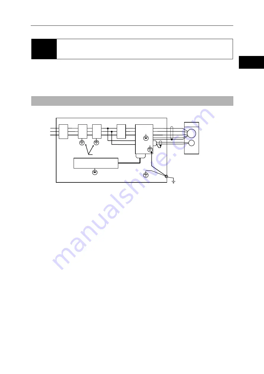
Grounding
Refer to the figure below when grounding all devices comprising the system.
*1: For information on grounding line filters, refer to [Installing noise filters] P2-15.
*2: FHA-17C to 40C actuators come with a shield connected to the body.
Grounding motor frame
When the actuator is grounded on the driven machine side through the frame, current flows
through the floating capacity (Cf) of the motor from the power circuit of the driver. To avoid
negative influence of the current, always connect the ground terminal (motor frame) of the
actuator to the ground terminal of the driver, and connect the ground terminal of the driver
directly to ground.
Grounding ducts
When the motor cables are housed in a metal conduit or a metal box, be sure to ground their
metal parts.
Always connect the ground at a single point.
HD
Noise
Filter
*1
・
Operation relay sequence, etc.
・
User signal generation circuit
CN2
E
R
S
T
U
V
W
CN1
HA-800A
Wire of 3.5mm
2
or larger
Grounding to the earth
(must be single-point grounding)
Wire of 3.5mm
2
or larger
Power input
3 phase
r
s
3.5mm
2
or larger
E
M
*2
Circuit
break
er
Surge
absor
ber
Magn
etic
switch
Summary of Contents for H A - 800A
Page 60: ...2 6 Wiring the host device 2 21 4 2 2 1 9 8 7 6 9 8 Installation wiring...
Page 86: ...3 6 Normal operation 3 25 4 3 3 1 9 8 7 6 9 8 Startup...
Page 152: ...5 8 Connection example in control mode 5 35 1 2 3 4 5 6 7 8 9 10 11 Appe I O signals...
Page 166: ...6 1 Operating display panel 6 13 11 10 9 4 7 6 5 4 3 2 1 Panel display and operation...
Page 206: ...8 2 Function extension parameter 8 17 1 2 3 4 5 6 7 8 9 10 11 Appe System parameter mode...
Page 222: ...9 2 Details of test mode 9 15 1 2 3 4 5 6 7 8 9 Test mode...
Page 270: ...11 2 Warnings and remedial actions 11 17 1 2 3 4 5 6 7 8 9 10 11 Appe Troubleshooting...
Page 271: ...1 16 Chapter 12 Option Options you can purchase as necessary are explained 12 1 Option 12 1...
Page 276: ...12 1 Option 12 5 1 2 3 4 5 6 7 8 12 Option...


