3-5 Manual gain adjustment method
3-19
4
3
3
1
9
8
7
6
9
8
Star
tup
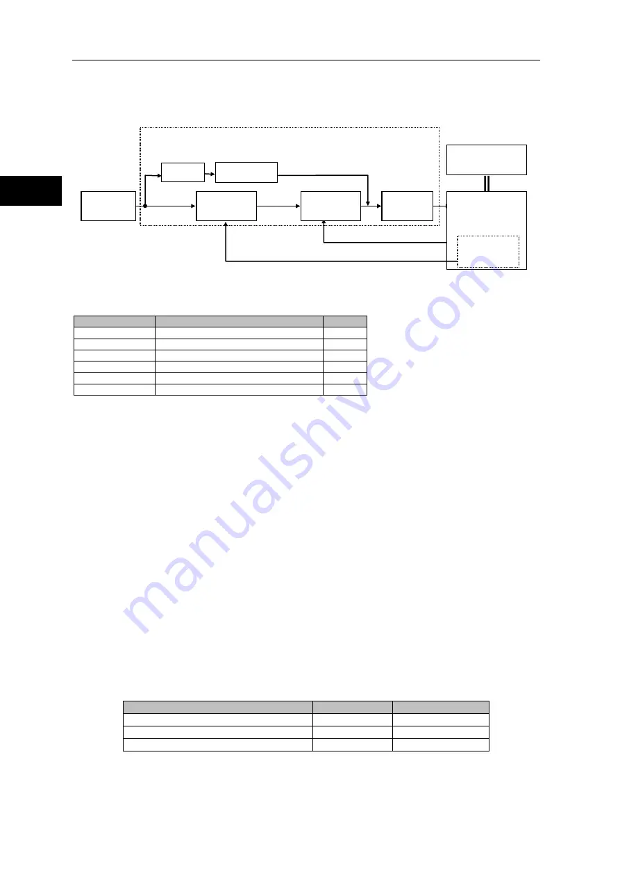
Block diagram of feed-forward control function
Parameters
The following parameters are used for feed-forward control.
Parameter No.
Description
Default
SP69
*1
Feed-forward control function setting
*2
AJ03
Feed-forward gain
0
AJ20
Feed-forward filter
1
AJ21
Load inertia moment ratio
100
AJ22
Torque constant compensation factor
100
AJ23
Spring constant compensation factor
100
*1: Changes to system parameter settings (SP00 to 79) are put into effect by changing the setting, then
turning control power supply OFF, then ON again.
*2: The default varies depending on the applicable actuator. Refer to [Default settings] (Apx-1) in the
appendix.
Adjustment details
Feed-forward control function setting (SP69)
・
Setting details
This sets the responsiveness when [SP69: Feed-forward control function setting] is [2, 3, or
4].The appropriate feed-forward filter frequency is set automatically based on the machine’s
resonance frequency due to the rigidity of the speed reducer in the actuator and the load
inertia moment ([AJ21: Load inertia moment ratio]).
When [SP69: Feed-forward control function setting] is [0, 1, or 5], [AJ20: Feed-forward filter]
can be set to any desired value.
・
Adjustment method
Normally, set [SP69=3: Normal operation mode].From the vibration and responsiveness, set
the appropriate operation mode, referencing the table below. The vibration and
responsiveness are greatly affected by [AJ03: Feed-forward gain].Also, for a low inertia ratio
(when [AJ21: Load inertia moment ratio] is 20 or less), vibration occurs particularly easily.
When the responsiveness is not satisfactory with [SP69=4: High-speed operation mode], you
can also adjust the feed-forward filter manually with [SP69=5: Manual tune mode].Only use
[SP69=1: Feed-forward control] when [SP69=5: Manual tune mode] cannot produce
satisfactory results.
Vibration
Responsiveness
SP69=2: Stable operation mode
Small
Low speed
SP69=3: Normal operation mode
Medium
Medium speed
SP69=4: High-speed operation mode
Large
High speed
HA-800A driver
Position
command
Speed feedback
Actuator
Position feedback
Feed-forward
control part
Differen-
tiation
Position
control part
Speed control
part
Power
amplifier
Mechanical load
system
Encoder
Summary of Contents for H A - 800A
Page 60: ...2 6 Wiring the host device 2 21 4 2 2 1 9 8 7 6 9 8 Installation wiring...
Page 86: ...3 6 Normal operation 3 25 4 3 3 1 9 8 7 6 9 8 Startup...
Page 152: ...5 8 Connection example in control mode 5 35 1 2 3 4 5 6 7 8 9 10 11 Appe I O signals...
Page 166: ...6 1 Operating display panel 6 13 11 10 9 4 7 6 5 4 3 2 1 Panel display and operation...
Page 206: ...8 2 Function extension parameter 8 17 1 2 3 4 5 6 7 8 9 10 11 Appe System parameter mode...
Page 222: ...9 2 Details of test mode 9 15 1 2 3 4 5 6 7 8 9 Test mode...
Page 270: ...11 2 Warnings and remedial actions 11 17 1 2 3 4 5 6 7 8 9 10 11 Appe Troubleshooting...
Page 271: ...1 16 Chapter 12 Option Options you can purchase as necessary are explained 12 1 Option 12 1...
Page 276: ...12 1 Option 12 5 1 2 3 4 5 6 7 8 12 Option...


