3-5 Manual gain adjustment method
3-16
4
3
3
1
Appe
10
Appe
11
7
6
5
Star
tup
Actuator
Adjustment details
Speed loop gain (AJ01)
This parameter is used to determine the response of the speed loop.
Increasing the set value of this parameter improves the response, but increasing the value
excessively causes the mechanical system to vibrate easily. On the other hand, a lower
response of the speed loop eliminates vibration but it may cause the response to drop. In
addition, setting the response of the speed loop too low can cause a delay in the external
position loop, thereby resulting in overshooting or the machine may vibrate as it executes a
speed command.
Speed loop integral compensation (AJ02)
The speed loop can be integrally compensated to reduce the negative effect of speed
fluctuation as the load fluctuates. The greater this integral compensation, the slower the
response becomes upon load fluctuation. On the other hand, a smaller compensation
improves the speed response upon load fluctuation, but too small a setting induces vibration.
Accordingly, adjust the integral vibration to an appropriate level.
Position loop gain (AJ00)
By increasing the position loop gain, you can improve the control response and shorten the
positioning time.
However, an excessively high gain causes overshooting and the machine will reverse at high
speed to compensate for the overshoot. These operations will be repeated and vibration will
occur.
If the position loop gain is too low, on the other hand, the control response drops.
Speed control
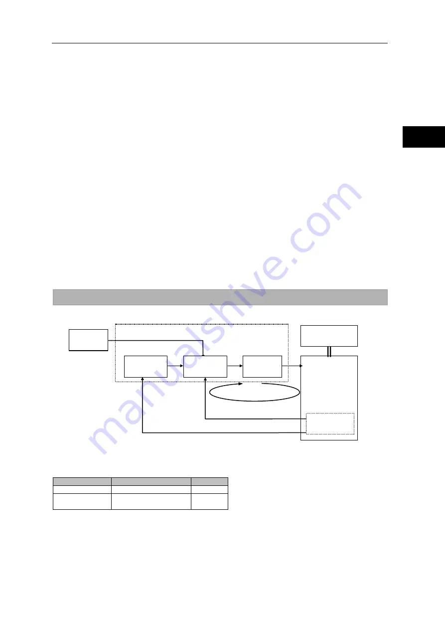
A block diagram of speed control is shown below.
Parameters
The following parameters are used to adjust the speed control gain.
Parameter No.
Description
Default
AJ01
Speed loop gain
*1
AJ02
Speed loop integral
compensation
*1
*1: The default varies depending on the applicable actuator. Refer to the values of applicable actuator that are
the targets of [Appendix: Default setting] (A-1).
Adjustment procedure
1
Perform rough adjustment via auto-tuning. Refer to [T09: Auto-tuning] (P9-11).
2
Set a larger speed loop integral compensation (AJ02).
HA-800A driver
Speed feedback
Position feedback
Speed loop
Speed
command
Position
control part
Speed control
part
Power
amplifier
Mechanical load
system
Encoder
Summary of Contents for H A - 800A
Page 60: ...2 6 Wiring the host device 2 21 4 2 2 1 9 8 7 6 9 8 Installation wiring...
Page 86: ...3 6 Normal operation 3 25 4 3 3 1 9 8 7 6 9 8 Startup...
Page 152: ...5 8 Connection example in control mode 5 35 1 2 3 4 5 6 7 8 9 10 11 Appe I O signals...
Page 166: ...6 1 Operating display panel 6 13 11 10 9 4 7 6 5 4 3 2 1 Panel display and operation...
Page 206: ...8 2 Function extension parameter 8 17 1 2 3 4 5 6 7 8 9 10 11 Appe System parameter mode...
Page 222: ...9 2 Details of test mode 9 15 1 2 3 4 5 6 7 8 9 Test mode...
Page 270: ...11 2 Warnings and remedial actions 11 17 1 2 3 4 5 6 7 8 9 10 11 Appe Troubleshooting...
Page 271: ...1 16 Chapter 12 Option Options you can purchase as necessary are explained 12 1 Option 12 1...
Page 276: ...12 1 Option 12 5 1 2 3 4 5 6 7 8 12 Option...


