10-9 Waveform monitoring
10-26
3
4
5
6
7
8
9
10
11
Appe
C
om
m
uni
cat
ion sof
tw
ar
e
10-9
Waveform monitoring
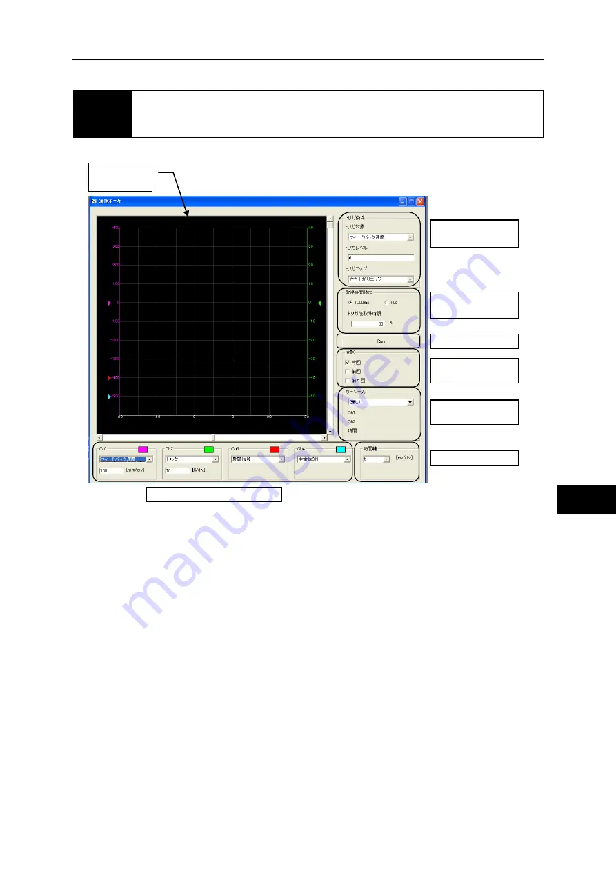
In addition to speed and torque, waveforms of various status signals can be displayed.
How to obtain waveform
1
Select the desired waveform using the waveform display selection.
Different speeds and torques can be selected for Ch1 and Ch2.After selecting the torque and
speed, also set the 1 division display.
2
Set the trigger condition.
3
Set the tracing time.
If "1000ms" is selected, you can set a desired value between 5 and 100 ms/div as the time
axis range to be displayed. If "10s" is selected, a desired value between 100 and 1,000 ms/div
can be selected. Select the time axis setting from the pull-down menu.
Waveform
display area
Trigger condition
setting
Tracing time setting
Start tracing
Waveform display
mode
Waveform
measurement
Time axis setting
Waveform display selection
Summary of Contents for H A - 800A
Page 60: ...2 6 Wiring the host device 2 21 4 2 2 1 9 8 7 6 9 8 Installation wiring...
Page 86: ...3 6 Normal operation 3 25 4 3 3 1 9 8 7 6 9 8 Startup...
Page 152: ...5 8 Connection example in control mode 5 35 1 2 3 4 5 6 7 8 9 10 11 Appe I O signals...
Page 166: ...6 1 Operating display panel 6 13 11 10 9 4 7 6 5 4 3 2 1 Panel display and operation...
Page 206: ...8 2 Function extension parameter 8 17 1 2 3 4 5 6 7 8 9 10 11 Appe System parameter mode...
Page 222: ...9 2 Details of test mode 9 15 1 2 3 4 5 6 7 8 9 Test mode...
Page 270: ...11 2 Warnings and remedial actions 11 17 1 2 3 4 5 6 7 8 9 10 11 Appe Troubleshooting...
Page 271: ...1 16 Chapter 12 Option Options you can purchase as necessary are explained 12 1 Option 12 1...
Page 276: ...12 1 Option 12 5 1 2 3 4 5 6 7 8 12 Option...


