


5-10
Chapter 5 FUNCTION SETTINGS AND OPERATIONS
5.9 Assigning Tool Numbers
Ths functon enables you to assgn tool holder 1 and tool holder to COND Nos. 1 to 8.
If the application software is used to perform pen exchange operations, "PROGRAM" must be selected for the
CONDITION PRIORITY setting (please see Section 5.27, "Using the Special Functions").
(1) Press the
[PAUSE] key
to select PAUSE mode.
(2) Press the
[NEXT] key
repeatedly untl the followng menu s dsplayed.
FORCE
OFFSET
SPEED
QUALITY
I/F FUNCTION
TOOL COND AREA OPT
(3) Press the
[F2] key
(TOOL COND) to dsplay the menu shown below.
FORCE
OFFSET
SPEED
QUALITY
THICK CUT LINE
TOOL No. ADJ.T POS
(4) Press the
[F2] key
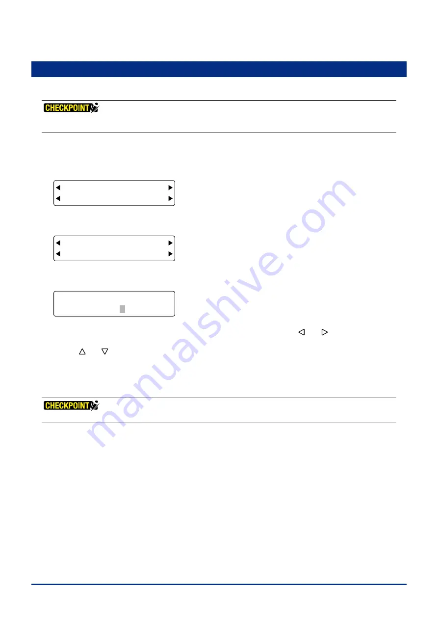
(TOOL No.) to dsplay the tool number assgnment settng screen.
FORCE
OFFSET
SPEED
QUALITY
COND No. 12345678
TOOL No. 11112222
The upper row of the dsplay represents the cuttng condton COND Nos. Use the
[ ]
or
[ ]
key
to move the
blnkng cursor underneath the CONDITION No. for whch you wsh to change the current tool assgnment, and then
use the
[ ]
or
[ ]
key
to toggle the tool number between 1 and 2.
The factory default settngs are those shown n the above screen.
Press the
[ENTER] key
to confirm your selections.
(5) Press the
[PAUSE] key
to cancel PAUSE mode.
These settings are retained in the plotter's internal memory even while the plotter is turned off.
Summary of Contents for FC2250 Series
Page 1: ...USER S MANUAL MANUAL NO FC2250 UM 151 FC2250 SERIES CUTTING PRO...
Page 105: ...5 29 Chapter 5 FUNCTION SETTINGS AND OPERATIONS Cutting Plotting Conditions List...
Page 111: ...CHAPTER 6 TROUBLESHOOTING PRODUCT SUMMARY 6 1 Troubleshooting 6 2 Error Messages...
Page 121: ...CHAPTER 8 SPECIFICATIONS PRODUCT SUMMARY 8 1 Main Specifications 8 2 External Dimensions...
Page 130: ......


