4-14
Chapter 4 REGISTRATION MARK SETTINGS AND DETECTION
4.8 Setting the Registration Mark Detection Judgment Level
Ths functon sets the color densty judgment level of the lne segments that are read durng a regstraton
mark detecton operaton. Ths level determnes the exstence of a lne segment by a change n densty of the
specified percentage from an area where there are no line segments (white area).
(1) Load a medum n the plotter.
(2) Press the
[PAUSE] key
to select PAUSE mode.
(3) Press the
[NEXT] key
repeatedly untl the followng menu s dsplayed.
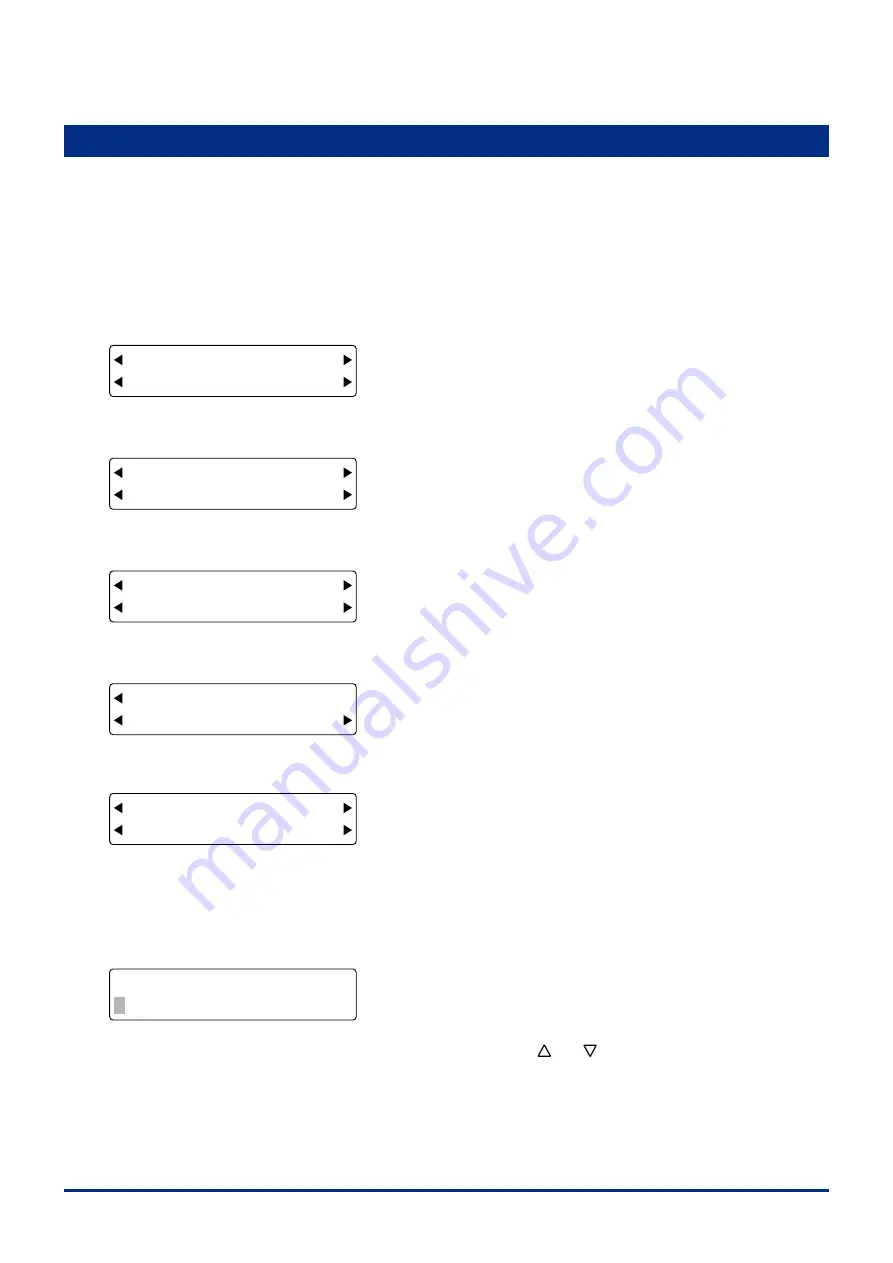
FORCE
OFFSET
SPEED
QUALITY
MARK TOOL U/D
BUFFER CLR. VIEW
(4) Press the
[F1] key
(MARK) to dsplay the regstraton mark functons selecton menu.
FORCE
OFFSET
SPEED
QUALITY
MODE DIST ADJ
TYPE OTHER SETUPS
(5) Press the
[F4] key
(OTHER SETUPS) to dsplay the menu shown below.
FORCE
OFFSET
SPEED
QUALITY
SIZE ADJ. SENS
ORG OFT SENS OPT
(6) Press the
[F4] key
(SENS OPT) to dsplay the menu shown below.
FORCE
OFFSET
SPEED
QUALITY
LEVEL
SENS SPD SENS STEP
(7) Press the
[F1] key
(LEVEL) to dsplay the menu shown below.
FORCE
OFFSET
SPEED
QUALITY
SENSOR ADJ TYPE 3
1,2 TYPE MIRROR
To set the level for regstraton mark patterns 1 and 2, press the
[F2] key
(1,2).
To set the level for regstraton mark pattern 3, press the
[F3] key
(TYPE 3).
To set the level for regstraton mark pattern Mrror 1 or Mrror 2, press the
[F4] key
(MIRROR).
(8) If the
[F2] key
(1,2) was pressed, the menu for settng the sensor level s dsplayed.
FORCE
OFFSET
SPEED
QUALITY
LEVEL SETTING: 1,2
X=70% Y=70%
Use the
[F2]
or
[F4] key
to move the blnkng cursor to X or Y, and the
[ ]
or
[ ]
key
to change the numerc value.
When the dsplayed settngs are satsfactory, press the
[ENTER] key
to confirm your selections.
Setting range: 1 to 99% [Default value: Registration mark pattern 1, 2 and MIRROR: X = 70, Y = 70;
Registration mark pattern 3: X = 85, Y = 85]
Select a numerc value that s approprate for the dfference between blank areas of the medum (areas where there
s no drawng) and the densty of the regstraton marks. Settng a hgher value enables hgher senstvty (fant
Summary of Contents for FC2250 Series
Page 1: ...USER S MANUAL MANUAL NO FC2250 UM 151 FC2250 SERIES CUTTING PRO...
Page 105: ...5 29 Chapter 5 FUNCTION SETTINGS AND OPERATIONS Cutting Plotting Conditions List...
Page 111: ...CHAPTER 6 TROUBLESHOOTING PRODUCT SUMMARY 6 1 Troubleshooting 6 2 Error Messages...
Page 121: ...CHAPTER 8 SPECIFICATIONS PRODUCT SUMMARY 8 1 Main Specifications 8 2 External Dimensions...
Page 130: ......


