GE M
EDICAL
S
YSTEMS
D
IRECTION
2380207, R
EVISION
7
LOGIQ™5 PRO S
ERVICE
M
ANUAL
5-24
Section 5-6 - Top Console
5-6-1-1
KEYBOARD Signal I/O
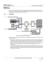
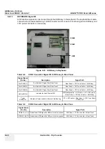
All of interface signals to console are through the HUB assy in the keyboard. The keyboard has 4 cable
connectors for console interfacing. 1 USB connector and 2 connectors for other signal on HUB assy and
1 DC power connector on main assy
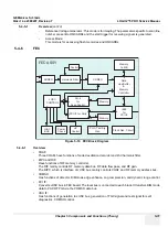
Figure 5-19 HUB Assy in Keyboard
Table 5-8
CON1 Connector Signal I/O to RDI assy in Rear Panel
Signal Name
(Pin No)
Description
Signal Path
Foot SW #1(1)
Foot Switch #1 Signal from Rear Panel
Rear Panel -> 10P Conn Cable -> HUB Assy
Foot SW #2(3)
Foot Switch #1 Signal from Rear Panel
Rear Panel -> 10P Conn Cable -> HUB Assy
Foot SW #3(5)
Foot Switch #1 Signal from Rear Panel
Rear Panel -> 10P Conn Cable -> HUB Assy
HDD LED(7,8)
Indicator for Hard Disk in BEP
BEP Motherboard -> 2P Cable -> VIC -> 50P cable -
> Rear Panel -> 10P Conn Cable -> HUB Assy
Power
Switch(10)
Momantry Power switch for System Cold Booting
VIC -> 50P cable -> Rear Panel -> 10P Conn Cable
-> HUB Asys
Table 5-9
CON3 Connector Signal I/O to RDI assy in Rear Pane
Signal Name
(Pin No)
Description
Signal Path
USB #1(1,2,3,4) Downstream USB signal for USB port in the rear panel
HUB Assy -> 13P conn cable -> Rear Panel
USB #2(7,8,9,10) Downstream USB signal for USB port in the rear panel
HUB Assy -> 13P conn cable -> Rear Panel
C O N 1
C O N 3
U S B
C O N 1
C O N 3
U S B
Summary of Contents for LOGIQ 5 PRO
Page 2: ...GE MEDICAL SYSTEMS DIRECTION 2407381 REVISION 7 LOGIQ 5 PRO SERVICE MANUAL Page 1 2 ...
Page 3: ......
Page 7: ...GE MEDICAL SYSTEMS DIRECTION 2380207 REVISION 7 LOGIQ 5 PRO SERVICE MANUAL ii iii ...
Page 462: ...GE MEDICAL SYSTEMS DIRECTION 2380207 REVISION 7 LOGIQ 5 PRO SERVICE MANUAL A 4 Index INDEX ...


