GE M
EDICAL
S
YSTEMS
D
IRECTION
2380207
, R
EVISION
7
LOGIQ™ 5 PRO S
ERVICE
M
ANUAL
Chapter 8 Replacement Procedures
8 - 93
8-7-3
BackPlane (FRU No. 502)
Purpose: This is a description on how to remove and replace the Backplane.
8-7-3-1
Tools
•
Common pillips screwdrivers
8-7-3-2
Needed Manpower
•
1 person, 30 m travel
8-7-3-3
Preparations
•
Shut Down the System and switch off the Main Breaker at the rear as described in section 4-3-2 on
•
Left Cover, Right Cover and Rear Cover should be removed before proceed. Refer to section 8-5-
1 on page 41, section 8-5-2 on page 43, and section 8-5-3 on page 45.
•
It is recommended to remove BEP (Back End Processor) assy before proceed. For more
information refer to section 8-8-1 on page 100
8-7-3-4
Removal Procedure
1.) Remove the EMI Cover R (FRU No.313). Refer to section 8-5-14 on page 66.
2.) Unscrew the nine (9) screws from the Nest EMI Cover.
3.) Remove the Nest EMI Cover.
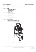
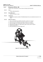
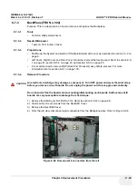
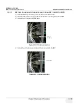
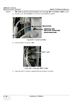
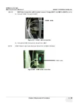
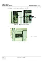
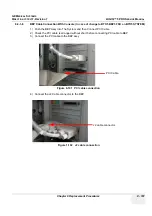
4.) From the left view, disconnect eight connectors from the Backplane Assy. Refer to Figure 8-84.
CAUTION
An electronic discharge may damage a component. Turn OFF power and wear the wrist strap
before you remove circuit boards. Do not unplug the power cord to keep ground continuity.
Do not bend or flex the boards when mounting/dismounting each boards. Surface mount IC
boards are very susceptible to damage from flex/torque.
Figure 8-84 Disconnect 8 connectors from the left
Summary of Contents for LOGIQ 5 PRO
Page 2: ...GE MEDICAL SYSTEMS DIRECTION 2407381 REVISION 7 LOGIQ 5 PRO SERVICE MANUAL Page 1 2 ...
Page 3: ......
Page 7: ...GE MEDICAL SYSTEMS DIRECTION 2380207 REVISION 7 LOGIQ 5 PRO SERVICE MANUAL ii iii ...
Page 462: ...GE MEDICAL SYSTEMS DIRECTION 2380207 REVISION 7 LOGIQ 5 PRO SERVICE MANUAL A 4 Index INDEX ...


