GE M
EDICAL
S
YSTEMS
D
IRECTION
2380207, R
EVISION
7
LOGIQ™5 PRO S
ERVICE
M
ANUAL
Chapter 5 Components and Functions (Theory)
5-7
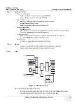
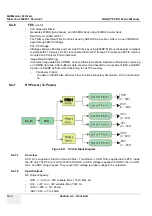
5-4-1-1
Interface to Probe
•
Probe Status detection
-
Detects whether or not a probe is connected.(POPEN)
-
Detects ID code of a connected probe.(PCODE)
•
Mux Interface
-
Transfers control data of Mux to a probe.(CONSYS,CONSTA)
-
Enables/Disables control of data.
-
Detects whether Mux data setting is finished or not.
•
Power Supply for Mux
-
Supply/Cut control:
+5V and +15V on a connector are supplied while a probe is connected to the connector.
+/-SHV are supplied only while a probe is selected.
•
Surface temperature
-
Detects resistance of a thermistor in a probe head as voltage when the probe is
selected.(PTEMP) This signal is connected to FEC.
•
LED Blinking
-
The LED in a probe blinks when the probe is selected.
5-4-1-2
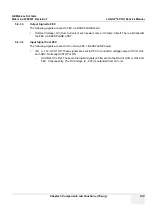
IIC bus
-
Connects signals of IIC bus with a relay when IIC bus access is required.
-
Selects one of three probes that IIC access with 3-to-1 switch.
5-4-2
LMT
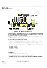
The main function of LMT ASSY is as follows.
-
64ch transmit/receiving switches protect a Pre-amp from a high voltage transmit pulse
-
All control signal and DC power for RLY pass through this LMT Assy
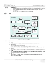
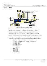
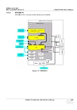
Figure 5-6 LMT Block Diagram
USB from BEP
USB#1, #2 From
Rear Panel
A/N Key Assy
USB
Track Ball
USB I/F
USB I/F
RS232
USB I/F
USB I/F
Down #2
Down #1
Down #4
Down #4
A/N Matrix
Interface
USB HUB
Function Key Arrys
Encoders
TGC SLide POT
LEDs for Key
backlight
Foot Switch I/F
USB
MICOM
With HUB
USB
MICOM
RAM
VGA Display from BEP
LCD Assy
AD
Board
Inverter
6.4"
TFT LCD
Touch
Sensor
Keyboard
Control
MICOM
Touch Screen
Interface
Summary of Contents for LOGIQ 5 PRO
Page 2: ...GE MEDICAL SYSTEMS DIRECTION 2407381 REVISION 7 LOGIQ 5 PRO SERVICE MANUAL Page 1 2 ...
Page 3: ......
Page 7: ...GE MEDICAL SYSTEMS DIRECTION 2380207 REVISION 7 LOGIQ 5 PRO SERVICE MANUAL ii iii ...
Page 462: ...GE MEDICAL SYSTEMS DIRECTION 2380207 REVISION 7 LOGIQ 5 PRO SERVICE MANUAL A 4 Index INDEX ...


