GE M
EDICAL
S
YSTEMS
D
IRECTION
2380207
, R
EVISION
7
LOGIQ™ 5 PRO S
ERVICE
M
ANUAL
Chapter 8 Replacement Procedures
8 - 165
8-9-6
Fuse Set (FRU No. 705)
Purpose: This is a description on how to remove and replace the Fuse Set.
8-9-6-1
Tools
•
Common pillips screwdrivers
•
Allen/Unbraco wrench
8-9-6-2
Needed Manpower
•
1 person, 15 m travel
8-9-6-3
Preparations
•
Shut Down the System and switch off the Main Breaker at the rear as described in section 4-3-2 on
8-9-6-4
Removal Procedure
NOTE:
Fuses can be removed without disassembling AC Power Assy.
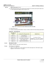
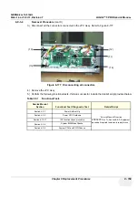
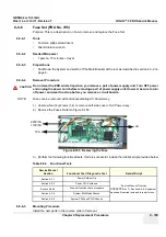
1.) Unscrew four (4) screws (1-4) to remove Left side cover of AC Power assy.
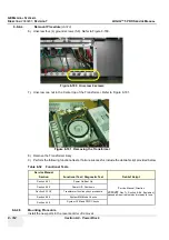
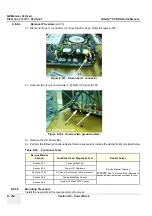
2.) Remove the Fuses. Refer to Figure 8-185.
3.) Perform the following functional tests. If all are successful, include the debrief script provided below.
8-9-6-5
Mounting Procedure
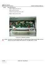
Install the new parts in the reverse order of removal.
CAUTION
Do not wear the ESD wrist strap when you remove a part of power supply unit. Turn OFF power
and unplug the power cord before removing a part of power supply unit. However be sure to turn
off power and wear the strap before you remove a circuit boards.
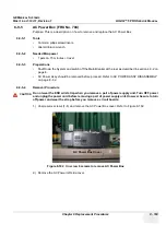
Figure 8-185 Removing the Fuse
Table 8-54 Functional Tests
Service Manual
Section
Functional Test / Diagnostic Test
Debrief Script
“Service Manual, Direction
2380207
, Rev 7+, Section 8-9-6. Equipment
passed all required tests and is ready for use. “
Fuse set function check procedure
3A
10A
220V/3A
110V/5A
Summary of Contents for LOGIQ 5 PRO
Page 2: ...GE MEDICAL SYSTEMS DIRECTION 2407381 REVISION 7 LOGIQ 5 PRO SERVICE MANUAL Page 1 2 ...
Page 3: ......
Page 7: ...GE MEDICAL SYSTEMS DIRECTION 2380207 REVISION 7 LOGIQ 5 PRO SERVICE MANUAL ii iii ...
Page 462: ...GE MEDICAL SYSTEMS DIRECTION 2380207 REVISION 7 LOGIQ 5 PRO SERVICE MANUAL A 4 Index INDEX ...


