MCT-CM
58
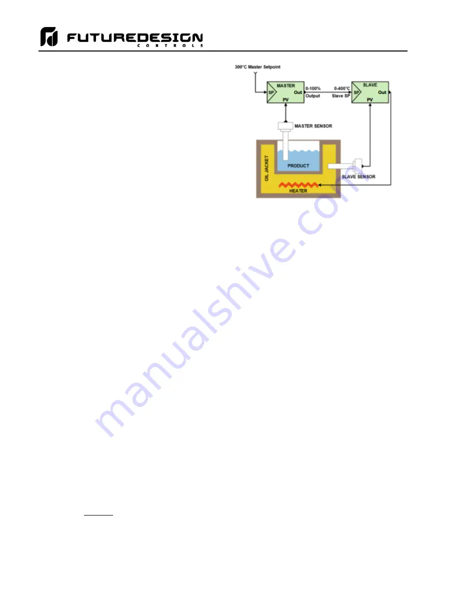
The maximum oil temperature is limited to a safe
operating range since it is now controlled directly.
The product temperature control generates a set
point of 0 to 400°C based on a 0 to 100% output.
Thus, the oil temperature will not exceed 400°C.
This also limits possible overshoot of the product
once it reaches set point. As the product approaches
set point, the control output decreases causing a drop
in the oil temperature set point. The oil temperature
control loop then immediately responds by reducing
its output to decrease oil temperature.
Ideally, as the product reaches its set point, the oil
temperature will also have decreased to a minimal
value over the product (in order to account for thermal
losses in the system) and thus hold the product at its
set point.
The advantage of cascade control, like in the example above, comes down to isolating a process with relatively
slow dynamics (like temperature, level, humidity) from some other relatively-fast process that has to be
manipulated to control the slow process. If the heating elements were directly immersed in the product, then
cascade control would most likely not be necessary as the heating elements would directly affect the product
temperature. Since the heating element affects oil temperature, and that in turn affects product temperature,
cascade control is necessary in order to properly control the system.
Cascade control does have disadvantages. One, it requires an additional measurement in order to work. Two,
there is an additional control that has to be tuned. And three, the control strategy is more complex, for engineers
and operators alike. These disadvantages have to be weighed up against the benefits of the expected
improvement in control to decide if cascade control should be implemented.
Cascade control is beneficial only if the dynamics of the inner loop are fast compared to those of the outer loop.
Cascade control should generally only be used if the inner loop is at least three times faster than the outer loop,
because the improved performance may not justify the added complexity. In addition to the diminished benefits
of cascade control when the inner loop is not significantly faster than the outer loop, there is also a risk of
interaction between the two loops that could result in instability. This is especially true if the inner loop is tuned
very aggressively.
If cascade operation is enabled for a loop, its set point will be calculated by the MCT based on the output of the
selected source loop. The MCT will then apply the set point automatically and override any other set point
entered for the loop. There are two modes of operation for the cascade control feature, deviation and process.
These modes define how the loop set point is calculated using the low and high set points.
Disabled:
Cascade control is not implemented and the loop runs independently of the others.
Deviation:
This mode
uses the low and high cascade set points to generate a set point that is defined relative
to the source loop set point. The upper and lower range of the loop set point is calculated by
adding the high and low set point values as offsets from the
source loop’s set point. As the set
point of the source loop changes, the window defined by the high and low set points automatically
changes with it.
Example:
If the source loop set point is 50, the cascade Low SetPoint is -10 and the High
SetPoint is 20, the loop set point will be in the range of 40 (50 - 10) to 70 (50 + 20).
The actual set point value is then calculated by using the percentage of output of the
source loop and creating a linear set point range from 40 to 70.
Summary of Contents for MCT-CM
Page 20: ...MCT CM 20...
Page 24: ...MCT CM 24...
Page 45: ...MCT CM 45...
Page 187: ...MCT CM 187...
Page 227: ...MCT CM 227 A 4 Control Module Specifications Main CPU...
Page 228: ...MCT CM 228...
Page 229: ...MCT CM 229...
Page 230: ...MCT CM 230...
Page 231: ...MCT CM 231 Analog I O Card...
Page 232: ...MCT CM 232...
Page 233: ...MCT CM 233 Digital Input Card...
Page 234: ...MCT CM 234...
Page 235: ...MCT CM 235 Digital Output Card...
Page 236: ...MCT CM 236...
Page 237: ...MCT CM 237 Dual Communications Card Barcode and Remote Display Communication Cartridges...
Page 238: ...MCT CM 238 A 5 Power Supply Specifications...
Page 239: ...MCT CM 239...
Page 240: ...MCT CM 240 A 6 Power On Delay Relay Specifications GE1A C10HA110...
Page 241: ...MCT CM 241...


