MCT-CM
149
Select
Off
to have the MCT default to the off state on power-up. If a program was running when power was
lost, the program will be stopped. In addition, all system events will be turned off. Note that loop controls will
maintain the last set point value prior to power loss with loop control outputs active (ON).
Select
Hold
to have the MCT return to operation at the same point it was prior to the power outage. If a program
was running, the program will still be active; however, it will remain in hold with the active set points and events
that it was operating under prior to losing power until manually set to continue.
Select
Continue
to have the MCT pick-up where it left off on loss of power. If a program was running prior to
the power outage, it will resume where it left off and continue through the rest of the program. Note that the set
point ramp will continue from the set point value at the time of power interruption unless the program is in the
‘ramp rate’ configuration.
Select
Start Over
to automatically restart the program that was running at power failure. Use this option if it is
critical for a program to run from start to finish without interruption.
Select
Resume
to have the MCT pick-up where it would be at the current time, if power had not been lost. If a
program was running prior to the power outage, the MCT will advance forward through the program to the point
where it would be, at the current time, and resume operation from that point.
NOTE:
When a program is NOT running and a power down/up sequence occurs, the MCT will return with the
same set points and system events active as when the power was lost. If a program stays in hold
regardless of power recovery configuration, refer to the OEM configuration provided by the installer.
Digital inputs may be used to place a program in hold. This input may have to be reset to allow the
program to continue.
9.8 Communication Settings
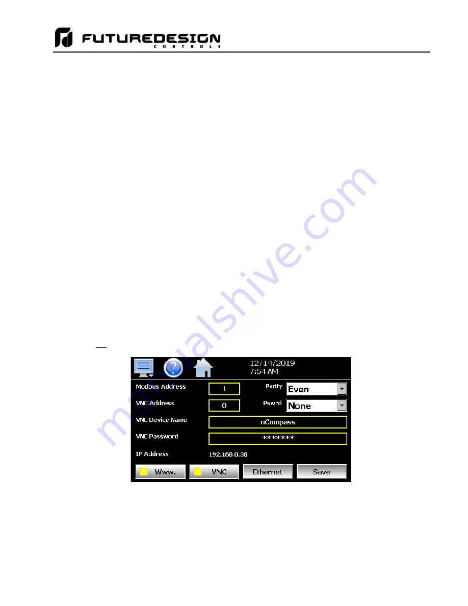
The “Comms” screen provides settings for the Modbus serial and TCP interfaces as well as the web server and
VNC interfaces. It also provides the MCT IP address, which is required for using the Modbus TCP, VNC and
web server interfaces. For more information regarding the use of the MCT data communications interfaces,
see section 11 Communications.
The
Modbus Address and Parity
settings are used to configure the serial interface for user communications.
Valid addresses are 1 to 247. The Modbus Address is also used to specify the unit ID for Modbus TCP
communications. Modbus TCP communications is provided over the Ethernet interface on port 502.
The
VNC Address and Password
set access rights to the MCT VNC server. Valid addresses are from 0 to
99. The VNC password selection defines the connection mode for the server. The selections are “None” and
“VncAuth” which requires users to enter the password when connecting to the MCT over the VNC interface.
Summary of Contents for MCT-CM
Page 20: ...MCT CM 20...
Page 24: ...MCT CM 24...
Page 45: ...MCT CM 45...
Page 187: ...MCT CM 187...
Page 227: ...MCT CM 227 A 4 Control Module Specifications Main CPU...
Page 228: ...MCT CM 228...
Page 229: ...MCT CM 229...
Page 230: ...MCT CM 230...
Page 231: ...MCT CM 231 Analog I O Card...
Page 232: ...MCT CM 232...
Page 233: ...MCT CM 233 Digital Input Card...
Page 234: ...MCT CM 234...
Page 235: ...MCT CM 235 Digital Output Card...
Page 236: ...MCT CM 236...
Page 237: ...MCT CM 237 Dual Communications Card Barcode and Remote Display Communication Cartridges...
Page 238: ...MCT CM 238 A 5 Power Supply Specifications...
Page 239: ...MCT CM 239...
Page 240: ...MCT CM 240 A 6 Power On Delay Relay Specifications GE1A C10HA110...
Page 241: ...MCT CM 241...


