MCT-CM
54
IMPORTANT: It is highly recommended that
“Auto Online” be disabled whenever the MCT display is used on
the system. This prevents system operation until the MCT application is initialized and ready
for operator input to control the system.
When using the auto online function, ensure that the automatic start of the MCT control module
upon application of power will not cause a hazardous condition. Operator control/monitoring
of the system will not be available until a software connection is made via MCT
’s user
communications port, or the MCT
’s local display is attached and the runtime application has
initialized.
Emergency stop, safety and interlocking circuits MUST be configured outside of the MCT. If
such circuits are made through the MCT, failure of the MCT may cause uncontrollable
operation, damage to equipment or accidents. The selection, application and use of Future
Design Control products and software is the sole responsibility of the OEM and/or end user.
Future Design Control will not be held responsible for any damages or losses, whether direct,
indirect, incidental, special or consequential, resulting from the use of Future Design Control
products or software.
4.2 Loop Setup
In order for the MCT to properly interface with each of the loop controls attached to the system, the MCT must
be given the proper configuration settings for each loop. These settings are accessed from the Loop Setup
screen under the Setup menu.
IMPORTANT: The loop input number corresponds to the communications address that must be manually set
in the loop control for the MCT to access it properly. If the communications address is not set
properly in the loop control, the MCT will not be able to communicate with it, or may
communicate with the wrong loop control and assign the incorrect set points and control
parameters to it.
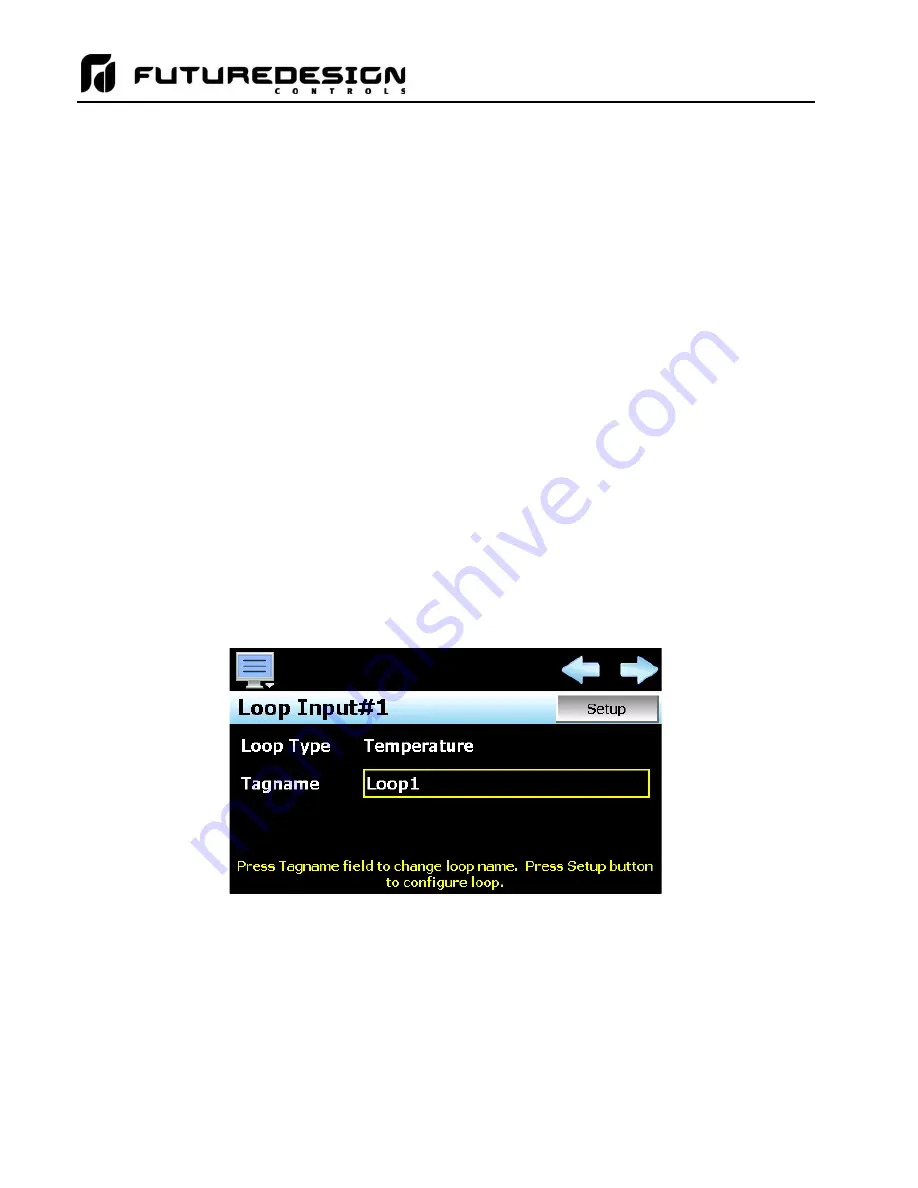
The left and right scroll (arrow) buttons allow the user access each loop in the system, by pressing left or right
to go to the previous or next loop.
The
Loop Type
is a display only field that allows the user to view the current input type setting of the loop. In
order to change the input type and access other settings for the loop input, press the
“Setup” button. This
provides access to the loop setup screen.
The
Tagname
field is used to enter a specific name for the loop, up to 11 characters in length. This name will
be used throughout the MCT runtime application and can be used to provide a more detailed description as to
the function of the loop in the application. Default tagnames are Loop1, Loop2, Loop3 and so on up to Loop10.
Summary of Contents for MCT-CM
Page 20: ...MCT CM 20...
Page 24: ...MCT CM 24...
Page 45: ...MCT CM 45...
Page 187: ...MCT CM 187...
Page 227: ...MCT CM 227 A 4 Control Module Specifications Main CPU...
Page 228: ...MCT CM 228...
Page 229: ...MCT CM 229...
Page 230: ...MCT CM 230...
Page 231: ...MCT CM 231 Analog I O Card...
Page 232: ...MCT CM 232...
Page 233: ...MCT CM 233 Digital Input Card...
Page 234: ...MCT CM 234...
Page 235: ...MCT CM 235 Digital Output Card...
Page 236: ...MCT CM 236...
Page 237: ...MCT CM 237 Dual Communications Card Barcode and Remote Display Communication Cartridges...
Page 238: ...MCT CM 238 A 5 Power Supply Specifications...
Page 239: ...MCT CM 239...
Page 240: ...MCT CM 240 A 6 Power On Delay Relay Specifications GE1A C10HA110...
Page 241: ...MCT CM 241...


