Summa Series Servodrive Product Manual
Fully-Closed Loop Control
Document Version: V1.01
(Dec, 2019)
© 2019 ESTUN Automation Co., Ltd. All right reserved.
10-3
10.3.1
Control Block Diagram
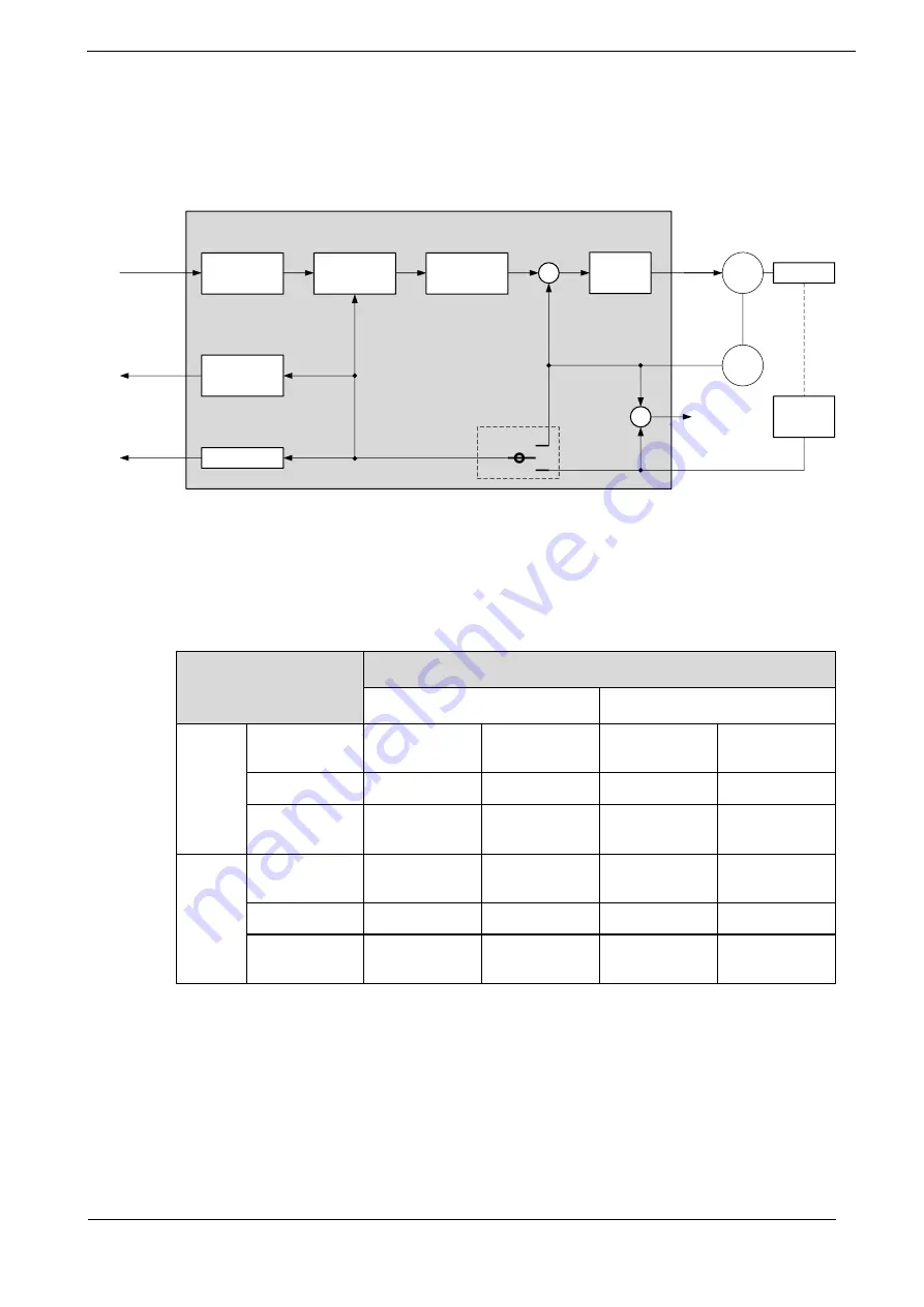
The control block diagram for fully-closed loop control is as shown in Figure 10-1.
Figure 10-1
Control block diagram for fully-closed loop control
Drive
Speed
loop
1/
Electronic
Gear Ratio
Divider
Pn200
EtherCAT
Feedback data
Encoder divided
pulse output
EtherCAT
reference
﹢
﹣
ENC
Motor Machine
External
encoder
Electronic
Gear Ratio
Deviation
counter
Positon
control loop
Alarm
detection
A.94
Pn210
10.3.2
Motor Direction and Machine Movement Direction Setting
You must set the Motor direction and the machine movement direction. To perform fully-closed loop
control, you must set the Motor rotation direction with both Pn001.0 (CCW, CW) and Pn210.3 (Direction
of External Encoder).
Pn001.0 (CCW, CW)
(1)
Pn210.3 (Direction of External Encoder)
0 (Not invert)
1 (Invert)
0
(CCW)
Reference
direction
Forward
reference
Reverse
reference
Forward
reference
Reverse
reference
Motor direction
CCW
CW
CCW
CW
External
encoder
(2)
Forward
movement
Reverse
movement
Reverse
movement
Forward
movement
1 (CW)
Reference
direction
Forward
reference
Reverse
reference
Forward
reference
Reverse
reference
Motor direction
CW
CCW
CW
CCW
External
encoder
Reverse
movement
Forward
movement
Forward
movement
Reverse
movement
(1): Phase B leads in the divided pulses for a forward reference regardless of the setting of Pn001.0.
(2): Forward direction: The direction in which the pulses are counted up. Reverse direction: The direction in which
the pulses are counted down.


