9-22
Disassembly and Assembly
Rev. I
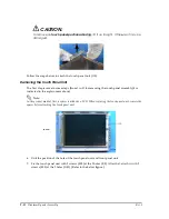
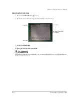
CAUTION:
To remove
the
touch panel position adjust jig,
lift it up straight. Otherwise it may be
damaged.
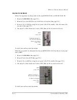
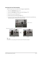
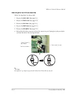
Follow the steps below to attach the touch panel unit (115).
Removing the Touch Panel Unit
The first step is same to some steps (from 1 to 5) for removing the touch panel assembly(it is
indicated in the explainment above).
Note:
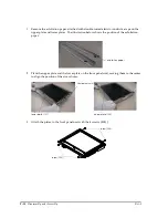
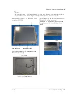
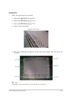
In the product made at first, a spacer is attched on LCD. When replacing the touch panel unit, remove the
spacer before attaching the touch panel unit.
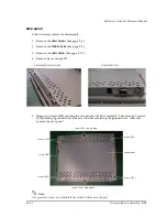
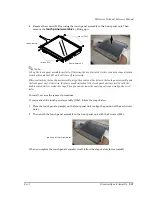
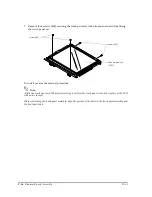
6. Unit the position of the hole of the touch panel unit and front panel unit.
7. Fix the touch panel unit with 2 screws (S05) at the 2 holes (E,F). After that, attach it with 2
screws (S05) at the 2 holes (G,H). (Refer to the below figure.)
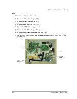
LCD
spacer
Summary of Contents for DM-M820
Page 1: ...Technical Reference Manual MR Series English 403308709 Rev I EPSON ...
Page 2: ......
Page 20: ...xviii Rev I ...
Page 42: ...2 8 Setup for the IM 800 and the DM M820 Rev I ...
Page 50: ...3 8 Hardware Specifications Rev I ...
Page 178: ...5 38 BIOS Functions Rev I ...
Page 216: ...8 26 Troubleshooting Rev I ...
Page 323: ......
Page 324: ...SEIKO EPSON CORPORATION EPSON ...

