Rev. I
Disassembly and Assembly
9-19
MR Series Technical Reference Manual
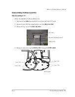
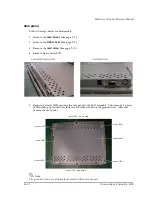
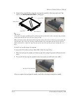
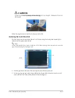
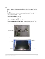
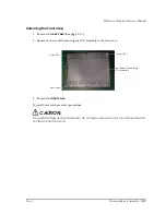
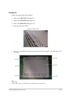
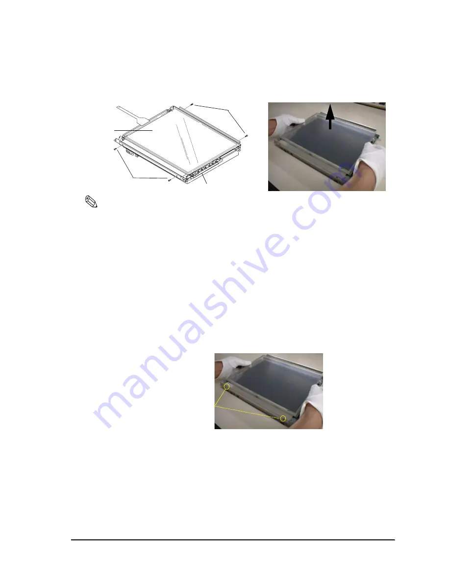
6. Remove the screws (S05) securing the touch panel assembly to the front panel unit. Then
remove the
touch panel assembly
by lifting up it.
Note:
Lift up the touch panel assembly carefully. Otherwise, the double-coated electric-conductive tape attached
to each plate and the LCD unit will come off incorrectly.
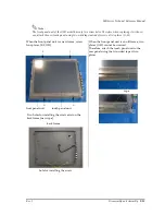
When reattaching the touch panel assembly, align the position of the holes in the touch panel assembly and
the front panel unit. Otherwise, the plates may be attached to the front panel unit incorrectly with the
double-coated electric-conductive tape. Then you cannot reuse the same tape after you realign the screw
holes.
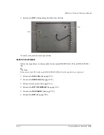
To install, reverse the removal procedure.
If you reattach the touch panel assembly (1056), follow the steps below.
1. Place the touch panel assembly on the front panel unit to align the position of the each screw
holes.
2. Then attach the touch panel assembly to the front panel unit with the 4 screws (S05).
When you replace the touch panel assembly itself, follow the steps below for reassembly:
screws (S05)
touch panel
screws (S05)
front panel unit
position of the screw holes
Summary of Contents for DM-M820
Page 1: ...Technical Reference Manual MR Series English 403308709 Rev I EPSON ...
Page 2: ......
Page 20: ...xviii Rev I ...
Page 42: ...2 8 Setup for the IM 800 and the DM M820 Rev I ...
Page 50: ...3 8 Hardware Specifications Rev I ...
Page 178: ...5 38 BIOS Functions Rev I ...
Page 216: ...8 26 Troubleshooting Rev I ...
Page 323: ......
Page 324: ...SEIKO EPSON CORPORATION EPSON ...

