


Rev. I
Disassembly and Assembly
9-43
MR Series Technical Reference Manual
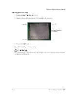
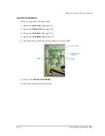
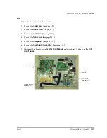
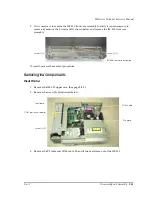
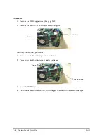
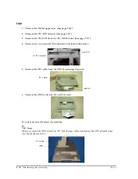
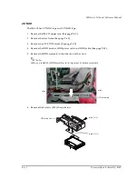
3. If it is necessary to remove the IM-800 front case assembly (usually it is not necessary to
remove it), remove the 5 screws (S11) shown below and remove the IM-800 front case
assembly.
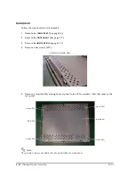
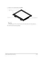
To install, reverse the removal procedure.
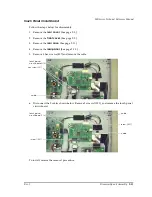
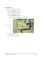
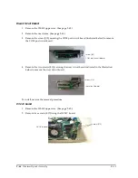
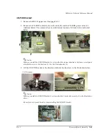
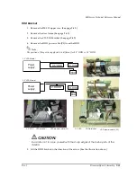
Removing the Compornents
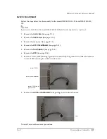
Riser Frame
1. Remove the IM-800 upper case. (See page 9-42.)
2. Remove the screw (S13) indicated below.
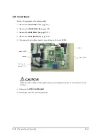
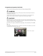
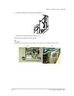
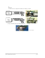
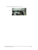
3. Remove the P2 cable and COM cable. Then lift the riser frame out of the IM-800.
screw (S11)
screw (S11)
IM-800 front case assembly
screw (S13)
riser frame
COM cable
COM port circuit board
P2 cable
Summary of Contents for DM-M820
Page 1: ...Technical Reference Manual MR Series English 403308709 Rev I EPSON ...
Page 2: ......
Page 20: ...xviii Rev I ...
Page 42: ...2 8 Setup for the IM 800 and the DM M820 Rev I ...
Page 50: ...3 8 Hardware Specifications Rev I ...
Page 178: ...5 38 BIOS Functions Rev I ...
Page 216: ...8 26 Troubleshooting Rev I ...
Page 323: ......
Page 324: ...SEIKO EPSON CORPORATION EPSON ...