Rev. I
BIOS Functions
5-13
MR series Technical Reference Manual
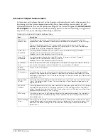
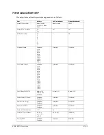
POWER MANAGEMENT SETUP Menu
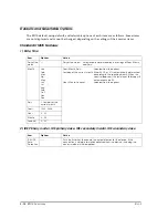
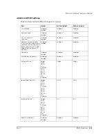
In this menu, set the items related to power management.
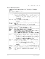
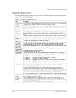
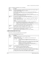
Onboard
Parallel Port
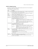
This setting enables/disables the parallel controller (combination of the I/O address and IRQ
resource for the parallel port) inside the S-I/O (W83627).
The default setting is "278/IRQ7".
There are 3 options, the "Disabled" setting, "378/IRQ7" setting and the "278/IRQ5" setting.
When using the "Disabled" setting, system resources can be opened and the port can be used
with other devices.
Make the necessary changes in accordance with the system configuration.
Note that since an 8-byte continuous I/O space is needed when setting the parallel port mode
to "EPP", the 3BC/IRQ7 setting cannot be used.
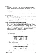
Parallel Port
Mode
This setting sets the parallel port mode. The default setting is "Normal".
There are 3 options, "Normal", "EPP" and "ECP". Make the necessary changes in accordance
with the system configuration.
Note that since an 8-byte continuous I/O space is needed when using the "EPP" setting, the
3BC/IRQ7 setting cannot be used.
In addition, a DMA channel number is required for the DMA transfer when using the "ECP"
setting.
The definitions for each mode are listed below.
Normal: Also called the SPP (Standard Parallel Port), this mode is for one direction only.
EPP:
EPP stands for Enhanced Parallel Port and is an improvement for the Normal mode I/O
throughput. EPP allows for faster data transfer than Normal mode.
ECP:
ECP stands for Extended Capabilities Port, and it is a mode that supports DMA transfer
and Run Length Enhanced. ECP allows for faster data transfer.
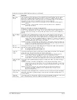
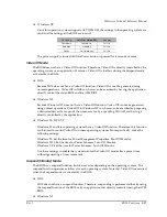
EPP Mode
Select
EPP Mode Select sets the type of EPP mode. The default setting is "EPP1.7".
There are 2 options, the EPP1.7 setting and the "EPP1.9 " setting.
Make the necessary changes in accordance with the system configuration.
ECP Mode Use
DMA
Sets the DMA channel number for the "ECP" and "ECP+EPP" setting.
The default setting is "3". There are 2 options, "1" and "3".
Make the necessary changes in accordance with the system configuration.
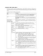
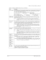
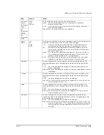
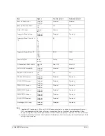
Table A-5 POWER MANAGEMENT SETUP menu
Items
Description
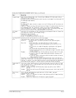
Video Off
Method
Sets the method to turn the monitor off for the Video Off Mode.
The default setting is DPMS.
Change the setting to match the system configuration (type of connected monitor).
The settings are explained below.
Bland Screen:
Use this setting when connecting an earlier version monitor that is
compatible with power management terminals that only have a video off
function.
V/H SYNC+Blank: This stops output of the horizontal sync signal, vertical sync signal, and display
signal from the video controller. Use this setting for monitors in which power
management is enabled when these signals end.
DPMS:
This activates BIOS control in accordance with the Display Power
Management System (DPMS) function of the video controller. The monitor
must be equipped with the DPMS function.
Video off In
Suspend
Use this setting to turn off the video when entering Suspend Mode.
The default setting is Off. Always use the default setting.
Off:
Choose this to stop video output in Suspend Mode.
On:
With this setting video output continues even in Suspend Mode.
MODEM Use IRQ
Use this setting on a system with a modem when access to the modem (IRQ resource trap) is
treated as a resume event from Suspend Mode or when the power is turned on by a ring signal
(when the Power On by Ring setting is set to Enabled). The default setting is NA.
This setting is the IRQ resource number allocated to the modem (serial port).
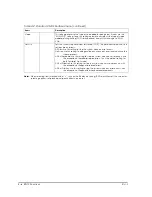
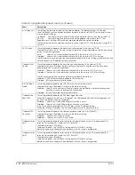
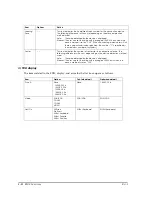
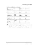
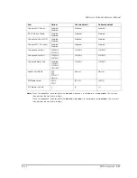
Table A-7 Integrated Peripherals menu (continued)
Items
Description
Summary of Contents for DM-M820
Page 1: ...Technical Reference Manual MR Series English 403308709 Rev I EPSON ...
Page 2: ......
Page 20: ...xviii Rev I ...
Page 42: ...2 8 Setup for the IM 800 and the DM M820 Rev I ...
Page 50: ...3 8 Hardware Specifications Rev I ...
Page 178: ...5 38 BIOS Functions Rev I ...
Page 216: ...8 26 Troubleshooting Rev I ...
Page 323: ......
Page 324: ...SEIKO EPSON CORPORATION EPSON ...


