9-4
Disassembly and Assembly
Rev. I
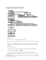
Conceptual Work Diagram for DM-M820
Note:
The above diagram is based on the DM-M820-014/024 model.
(*1) It is necessary for DM-M820-013/023 to do the procedures marked by an asterisk (*) in the diagram
above.
(*2)
It is necessary for DM-M820-015/025 to do without the procedures marked by an asterisk (*) in the
diagram above. So to disassemble and assemble the this model, read the explanation without an MSR in
this chapter.
How to use this diagram:
1. Search for the target part enclosed in a solid line (not parts enclosed in a dotted line).
2. Trace the line from the target part to
START
.
3. You must remove all the parts or units shown on the route that you have traced.
Note that the steps of disconnecting cables and removing plates on the units are not described in
this key map.
Rear cover (103)
Front cover (102)
Rear case (108)
LCD circuit board
(111)
Touch panel circuit board
(116)
Inverter circuit board
(112)
LCD (110)
MSR assembly (106)
LED circuit board (1045)
Base assembly (117)
Top cover of
Base assembly
Switch circuit board
(113)
(*)
(*)
(*)
(*)
Front case (109)
Touch panel assembly (1056)
or Touch panel unit (115)
Hinge Assemblies (118)
Rear panel (1042)
Rear case attached
with Base assembly
Front case (109)
DC Jack board
(122)
Summary of Contents for DM-M820
Page 1: ...Technical Reference Manual MR Series English 403308709 Rev I EPSON ...
Page 2: ......
Page 20: ...xviii Rev I ...
Page 42: ...2 8 Setup for the IM 800 and the DM M820 Rev I ...
Page 50: ...3 8 Hardware Specifications Rev I ...
Page 178: ...5 38 BIOS Functions Rev I ...
Page 216: ...8 26 Troubleshooting Rev I ...
Page 323: ......
Page 324: ...SEIKO EPSON CORPORATION EPSON ...


