9-26
Disassembly and Assembly
Rev. I
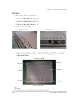
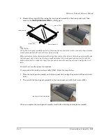
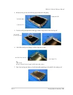
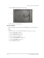
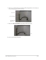
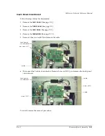
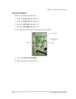
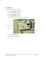
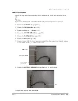
7. Remove 1 screw (1050) holding 1 ground wire and lift up the ground wire. After that remove
1 screw (1050) securing the switch circuit board
.
.
8. Remove the
switch circuit board
while pulling the cable from the hole.
To install, reverse the removal procedure.
screw (1050) and
ground wire
screw (1050)
switch circuit board
hole
Summary of Contents for DM-M820
Page 1: ...Technical Reference Manual MR Series English 403308709 Rev I EPSON ...
Page 2: ......
Page 20: ...xviii Rev I ...
Page 42: ...2 8 Setup for the IM 800 and the DM M820 Rev I ...
Page 50: ...3 8 Hardware Specifications Rev I ...
Page 178: ...5 38 BIOS Functions Rev I ...
Page 216: ...8 26 Troubleshooting Rev I ...
Page 323: ......
Page 324: ...SEIKO EPSON CORPORATION EPSON ...


