


9-12
Disassembly and Assembly
Rev. I
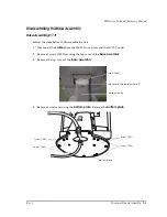
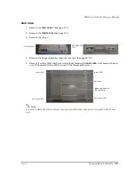
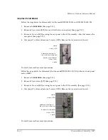
Removing the Front Case
1. Remove the
rear case.
(See page 9-11.)
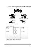
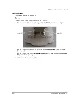
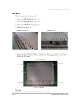
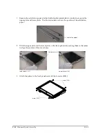
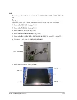
2. Remove 2 screws (S15) securing the LCD assembly to the front case. After then remove 2
screws (S05) holding 2 ground wires (one on each side) and lift up the ground wires. (The
model with a touch panel is used in the illustration below.)
Note:
The ground wires are not attached to the model without a touch panel.
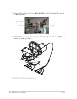
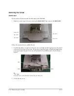
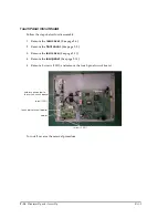
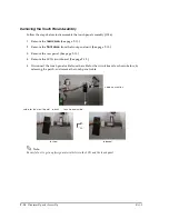
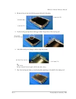
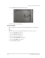
3. Remove the front
panel
unit holding LCD assembly from the
front case
. (See the
illustration above.)
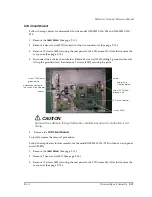
To install, reverse the removal procedure.
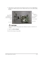
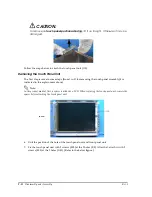
CAUTION:
To avoid damage during reassembly, do not apply pressure to any circuit boards when
you fasten them in place.
screw (S15)
front case
front panel unit holding
LCD assembly
screw (S05 ) and ground wire
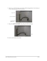
cable shown in top photo
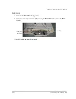
screw (S05)
screw (S15)
screw (S05 ) and ground wire
Summary of Contents for DM-M820
Page 1: ...Technical Reference Manual MR Series English 403308709 Rev I EPSON ...
Page 2: ......
Page 20: ...xviii Rev I ...
Page 42: ...2 8 Setup for the IM 800 and the DM M820 Rev I ...
Page 50: ...3 8 Hardware Specifications Rev I ...
Page 178: ...5 38 BIOS Functions Rev I ...
Page 216: ...8 26 Troubleshooting Rev I ...
Page 323: ......
Page 324: ...SEIKO EPSON CORPORATION EPSON ...