8-24
Troubleshooting
Rev. I
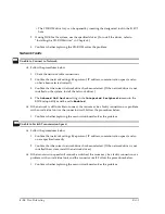
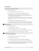
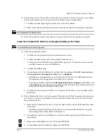
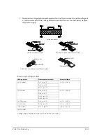
5. Measure the voltage between each terminal on the 20-pin connector and the voltage of
all drive connectors. If the voltage differs from that shown on the chart below, replace
the power supply.
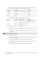
* Voltage range when electric current of 1A and more is consumed.
Power supply voltage check
Voltage system
Measurement terminals
Normal voltage
+3.3 V system
Pin 1 – pin 15
+ 3.14 ~ + 3.47 V
Pin 2 – pin 15
Pin 11 – pin 15
+5 V system
Pin 4 – pin 15
+ 4.75 ~ + 5.25 V*
Pin 6 – pin 15
Pin 19 – pin 15
Pin 20 – pin 15
+5 VSB system
Pin 9 – pin 15
+ 4.75 ~ + 5.25 V
+12 V system
Pin 10 – pin 15
+ 11.4 ~ + 12.6 V
–12 V system
Pin 12 – pin 15
– 10.8 ~ – 13.2 V
+24 V system
1
11
10
20
20-pin connector
HDD End of Power Cable
COM Port Circuit Board End of Power Cable
FDD and CD-ROM End of Power Cable
Black(GND)
12V)
Black(+24V)
White(GND)
Summary of Contents for DM-M820
Page 1: ...Technical Reference Manual MR Series English 403308709 Rev I EPSON ...
Page 2: ......
Page 20: ...xviii Rev I ...
Page 42: ...2 8 Setup for the IM 800 and the DM M820 Rev I ...
Page 50: ...3 8 Hardware Specifications Rev I ...
Page 178: ...5 38 BIOS Functions Rev I ...
Page 216: ...8 26 Troubleshooting Rev I ...
Page 323: ......
Page 324: ...SEIKO EPSON CORPORATION EPSON ...

