9-10
Disassembly and Assembly
Rev. I
Removing the Components (SERIAL NO. *xxxx00xxxx*)
When removing the components for which the SERIAL NO is *xxxx01xxxx*, see page 9-27.
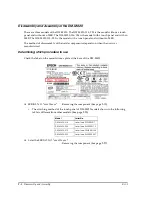
MSR Assembly or LED Circuit Board
1. Remove the
rear cover
. (See page 9-8.)
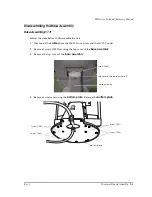
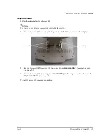
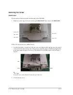
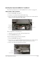
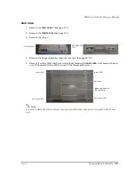
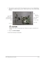
2. Disconnect 1 screw (S01) and remove the front cable clamp.
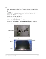
3. Remove 3 screws (S01) securing the MSR assembly to the front cover. And disconnect the
connector of the LED cable from the MSR assembly.
Follow the steps below to assemble the unit.
1. Confirm the connection of the cables, following the figure above.
2. Install the
rear cover
. (See page 9-8.)
To replace the LED circuit board, follow the steps below..
1. Remove the
rear cover
. (See page 9-8.)
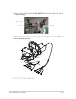
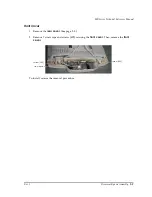
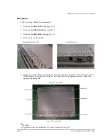
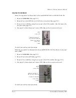
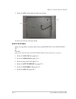
2. Remove 3 screws securing (S01) the MSR assembly to the front cover. And disconnect the
connector of the LED cable from the MSR assembly. (See the illustration above.)
3. Remove 1 screw (S03) securing the LED circuit board.
cable clamp
screw (S10)
screw (S10)
LED cable
MSR
)
screw (S01)
LED circuit board
screw (S03)
Summary of Contents for DM-M820
Page 1: ...Technical Reference Manual MR Series English 403308709 Rev I EPSON ...
Page 2: ......
Page 20: ...xviii Rev I ...
Page 42: ...2 8 Setup for the IM 800 and the DM M820 Rev I ...
Page 50: ...3 8 Hardware Specifications Rev I ...
Page 178: ...5 38 BIOS Functions Rev I ...
Page 216: ...8 26 Troubleshooting Rev I ...
Page 323: ......
Page 324: ...SEIKO EPSON CORPORATION EPSON ...


