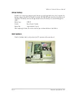
2-4
Setup for the IM-800 and the DM-M820
Rev. I
Note:
If you are using a DM-M820 with a touch panel, be sure to connect the serial port connector to
COM1 or COM2. Do not use COM3 or COM4.
Also if you are using a DM-M820 with a touch panel, do not install a mouse driver. Installing a
mouse driver can prevent the touch panel from working.
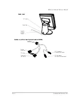
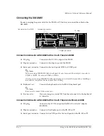
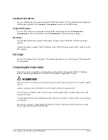
Connector Cables for a DM-M820 with No Touch Panel and No MSR
❏
DC plug
Connect to the 12 VDC output of the IM-800 or AC adapter
(OI-MR01).
❏
Display connector
Connect to the display port of the IM-800 or PC.
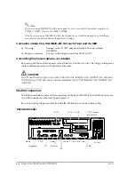
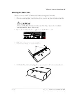
Connecting the Power Cable for AC Adapter
Be sure to push the end of the power cable all the way into the AC inlet. The fitting on the power
cable should make contact with the back of the inlet.
CAUTION:
Do not use the DC plug on a system other than the IM-800 or the OI-MR01 (AC adapter).
The DC plug on the exclusive cable is designed only for the IM-800 or the OI-MR01 (AC
adapter).
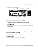
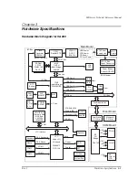
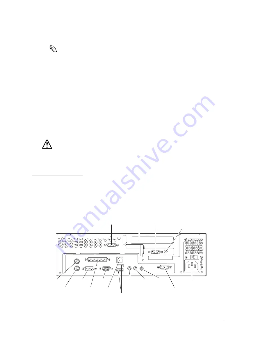
IM-800 Connectors
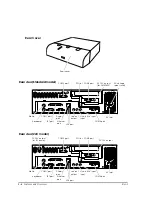
The illustration below shows all the connectors on the back of the IM-800. In addition, there are
two USB connectors on the front. (See Chapter 1.)
Be sure to unplug the power cable from the IM-800 before you connect these cables.
COM2
PCI slot COM3
12 VDC output
for DM-M820
Mouse
Keyboard
COM1
LPT
Display
USB
Ethernet
Line-out
Line-in
COM4
AC Inlet
Mic input
Standard model
Summary of Contents for DM-M820
Page 1: ...Technical Reference Manual MR Series English 403308709 Rev I EPSON ...
Page 2: ......
Page 20: ...xviii Rev I ...
Page 42: ...2 8 Setup for the IM 800 and the DM M820 Rev I ...
Page 50: ...3 8 Hardware Specifications Rev I ...
Page 178: ...5 38 BIOS Functions Rev I ...
Page 216: ...8 26 Troubleshooting Rev I ...
Page 323: ......
Page 324: ...SEIKO EPSON CORPORATION EPSON ...

