Step 3
Draw the detection rule.
a. Click to draw a rectangle on the surveillance video image. Right-click the image to
stop drawing.
b. Click to draw the minimum size or maximum size to filter the target.
The system triggers an alarm only when the size of detected target is between the
maximum size and the minimum size.
Click to delete the drawn size.
c. Configure the rule name and duration.
d. Click OK.
Step 4
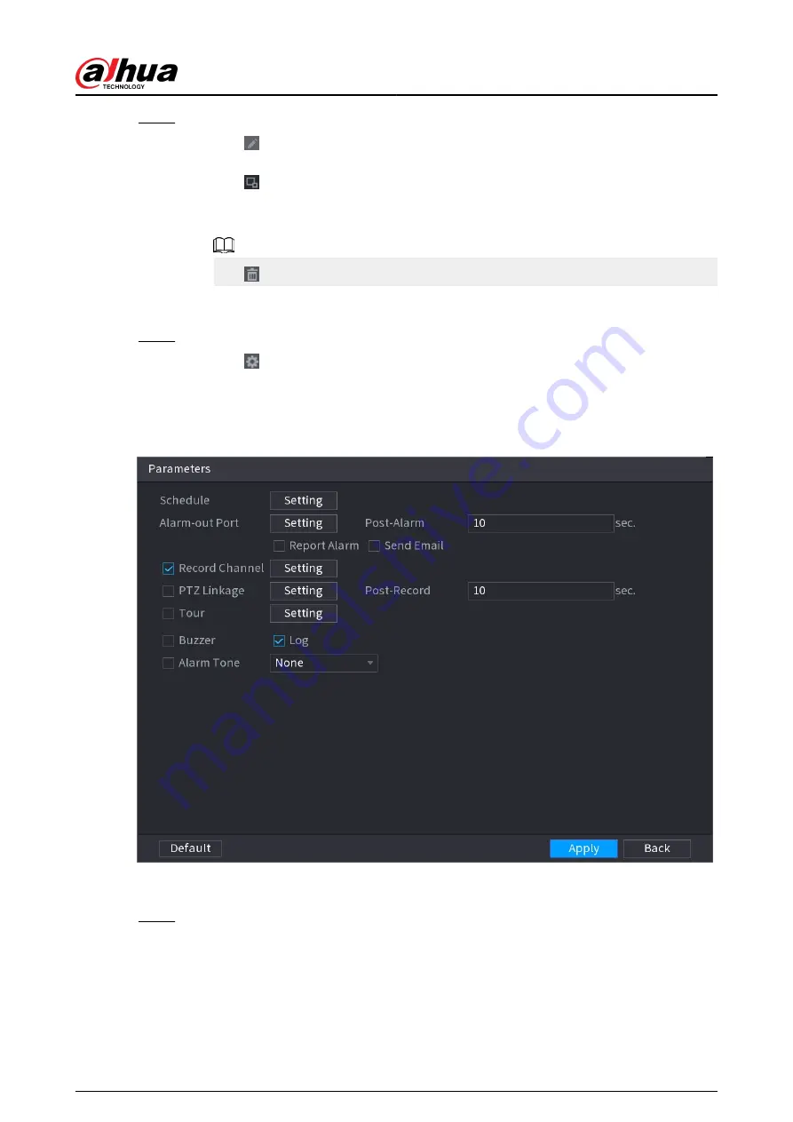
Configure alarm schedule and linkage.
a. Click .
b. Click Setting next to Schedule to configure the alarm period.
The system performs linkage actions only for alarms during the arming period.
Figure 5-183 Schedule and alarm linkage
c. Configure alarm linkage. For details, see Table 5-47 .
d. Click Apply.
Step 5
Click Apply.
User's Manual
296
Summary of Contents for NVR2104-I2
Page 1: ...ZHEJIANG DAHUA VISION TECHNOLOGY CO LTD V2 3 3 Network Video Recorder User s Manual...
Page 84: ...Figure 2 98 Alarm input port 1 User s Manual 71...
Page 132: ...Figure 5 8 Unlock pattern login User s Manual 119...
Page 147: ...Figure 5 23 AcuPick human detection User s Manual 134...
Page 151: ...Figure 5 27 Shortcut menu 1 User s Manual 138...
Page 217: ...Figure 5 93 Custom search 2 Step 8 Configure the search conditions as needed User s Manual 204...
Page 326: ...Figure 5 197 TCP IP Step 2 Click to configure the NIC card and then click OK User s Manual 313...
Page 376: ...Figure 5 247 Pattern login User s Manual 363...
Page 412: ...Figure 5 285 File management Step 2 Click Add User s Manual 399...


