


8-36
62-11039
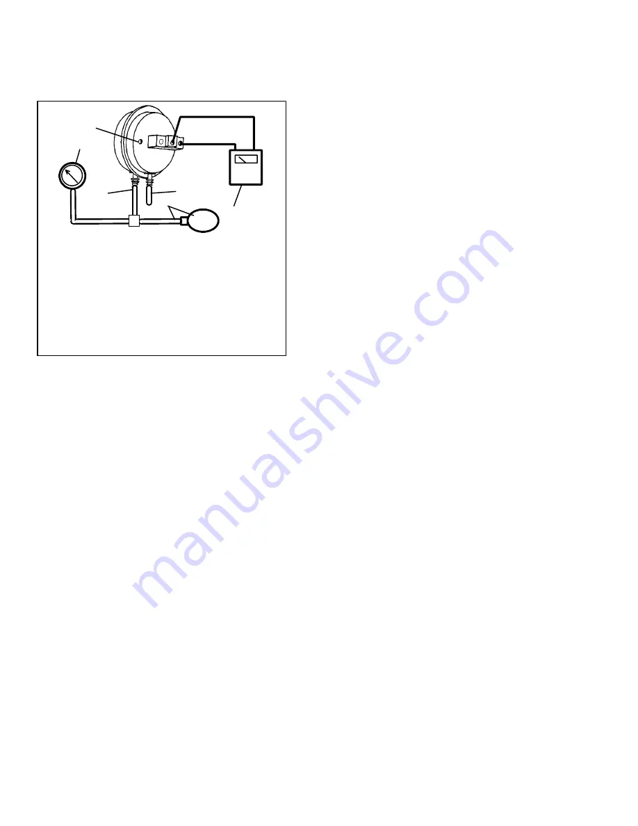
8.24.2 Electronic Defrost Timer
Refer to Section 2.12 for description.
8.25 CHECKING CALIBRATION OF
DEFROST AIR SWITCH
2
1
3
6
5
4
1. Ohmmeter or Continuity Device
2. Adjustment Screw (0.050” socket head
size)
3. Low Side Connection
4. Pressure Line or Aspirator Bulb (P/N
07-00177-01)
5. Magnehelic Gauge (P/N 07-00177-00)
6. High Side Connection
Figure 8--36 Defrost Air Switch Test Setup
a. Make sure magnehelic gauge is in proper calibra-
tion.
NOTE
The Magnehelic Gauge may be used in any
position, but must be re-zeroed if position of
gauge is changed from vertical to horizontal or
vice versa. USE ONLY IN POSITION FOR
WHICH IT IS ZEROED. The Defrost Air Switch
MUST be in the same orientation as it will be in
when installed in the unit.
b. With air switch in vertical position, connect high pres-
sure side of magnehelic gauge to high side connec-
tion of air switch. (See Figure 8--36)
c. Install tee in pressure line to high side connection. Tee
should be approximately half-way between gauge and
air switch or an improper reading may result.
d. Attach an ohmmeter to the air switch electrical con-
tacts to check switch action.
NOTE
Use a hand aspirator (P/N 07-00177-01), since
blowing into tube by mouth may cause an incor-
rect reading.
e. With the gauge reading at zero, apply air pressure
very slowly to the air switch. An ohmmeter will indi-
cate continuity when switch actuates. The switch
contacts should close and the ohmmeter needle
move rapidly to 0. Any hesitation in the ohmmeter
indicates a possible problem with the switch, and it
should be replaced.
f. Refer to Section 2.12 for switch settings. If switch fails
to actuate at correct gauge reading, adjust switch by
turning adjusting screw clockwise to increase setting or
counterclockwise to decrease setting.
g. Repeat checkout procedure until switch actuates at
correct gauge reading.
h. After switch is adjusted, place a small amount of
paint or fingernail polish on the adjusting screw so
that vibration will not change switch setting.
8.26 EVAPORATOR COIL
8.26.1 Cleaning
The use of recycled cardboard cartons is increasing
across the country. The recycled cardboard cartons
create much more fiber dust during transport than “new”
cartons. The fiber dust and particles are drawn into the
evaporator where they lodge between the evaporator
fins. If the coil is not cleaned on a regular basis,
sometimes as often as after each trip, the accumulation
can be great enough to restrict air flow, cause coil icing,
repetitive defrosts and loss of unit capacity. Due to the
“washing” action of normal defrost the fiber dust and
particles may not be visible on the face of the coil but
may accumulate deep within.
It is recommended to clean the evaporator coil on a
regular basis, not only to remove cardboard dust, but to
remove any grease or oil film which sometimes coats
the fins and prevents water from draining into the drain
pan.
Cardboard fiber particles after being wetted and dried
several times can be very hard to remove. Therefore,
several washings may be necessary.
a. Remove rubber check valves (Kazoo) from drain
lines (front of trailer or rail car).
b. Spray coil with a mild detergent solution such as
Oakite 164 or 202) or any good commercial grade au-
tomatic dish washer detergent such as Electrosol or
Cascade and let the solution stand for a few minutes
and reverse flush (opposite normal air flow) with clean
water at mild pressure. A garden hose with spray
nozzle is usually sufficient. Make sure drain lines are
clean.
c. Run unit until defrost mode can be initiated to check
for proper draining from drain pan.
8.26.2 Coil Replacement -- Compartment 1
a. Pump unit down. (Refer to section 8.10)
b. With power OFF and power plug removed, remove
the screws securing the panel covering the evapora-
tor section.
c. Disconnect all heater wiring.
d. Disconnect the RAT, DTT, and SAT sensors from the
coil.
e. Remove the mounting hardware from the coil.
f. Unsolder the two coil connections, one at the distrib-
utor and the other at the coil header.
g. After defective coil is removed from unit, remove
heaters and install on replacement coil.
h. Install coil assembly by reversing above steps.
i. Leak check connections per section 8.11. Evacuate
the unit per section 8.12 and add refrigerant charge
per Section 8.12.4.
Summary of Contents for VECTOR 1800 MT
Page 1: ......
Page 2: ...OPERATION SERVICE MANUAL for VECTOR 1800 MT Trailer Multi Temp Refrigeration Units ...
Page 19: ...1 5 62 11039 1 3 SAFETY DECALS ...
Page 20: ...1 6 62 11039 62 03958 00 Heat Warning 62 03957 01 High Voltage 62 60280 00 Standby Safety ...
Page 21: ...1 7 62 11039 ...
Page 303: ...10 1 62 11039 ...
Page 310: ...10 8 62 11039 BASED ON ENGINEERING SCHEMATIC 62 60926 REV G NEXT SHT ...
Page 311: ...10 9 62 11039 FROM PREVIOUS SHT ...


