


8-25
62-11039
c. Adding Oil To Service Replacement Compressor
NOTE
1. Service replacement compressors are
shipped without oil.
2. When first adding oil to the compressor,
add only 6.3 pints (3 liters) to the
compressor. Run the unit for 20 minutes in
cooling mode. Check the oil level in the
compressor sight glass. Add oil as
necessary. This procedure is designed to
compensate for excess oil that may have
migrated with refrigerant to other parts of
the system during unit operation.
d. Removing oil from the compressor
1. If the oil level recorded in step a.3. is above one-
eighth level of the capacity of the sight glass, oil must
be removed from the compressor.
2. Close (frontseat) suction service valve and pump
unit down to 2 to 4 psig (0.1 to 0.3 bar). Frontseat dis-
charge service valve and slowly bleed remaining re-
frigerant.
3. Remove the oil drain plug on the bottom plate of the
compressor and drain the proper amount of oil from
the compressor to obtain the correct level (maximum
is one-eight level of the sight glass). Replace the
plug securely back into the compressor.
DO NOT
FORGET TO OPEN SUCTION AND DISCHARGE
SERVICE VALVES.
4. Repeat step a.3 to ensure proper oil level.
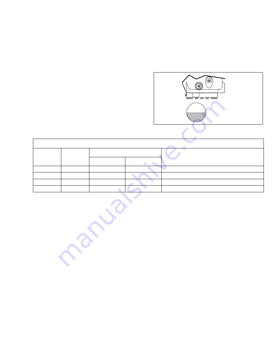
-- Maximum
-- Minimum
Figure 8--26. Oil Level in Sight Glass
Table 8-3 Compressor Torque Values
SIZE
TORQUE RANGE
SIZE
DIAMETER THREADS
TORQUE RANGE
USAGE
DIAMETER
(INCHES)
THREADS
PER INCH
FT LB
MKG
USAGE
(INCHES)
PER INCH
FT-LB
MKG
1/4
28
12 -- 16
1.66 -- 2.21
Unloader Valve
5/16
18
20 -- 30
2.77 -- 4.15
Discharge Valve
3/8
16
40 -- 50
5.53 -- 6.92
Cylinder Head
1/2
13
65--70
9.0--9.7
Suction Valve
8.15 COMPRESSOR UNLOADER VALVE
The compressor unloaders (located on the compressor
cylinder heads) are controlled by the Advance
Microprocessor. (Refer to Section 2.3.3)
a. Manual Checkout procedure
1. Initiate Pretrip.
2. Connect manifold gauges to the compressor suction
and discharge service valves and start unit in cooling
with the trailer temperature at least 5
_
F (2.8
_
C)
above set point and the compressor will be fully
loaded (both unloader coils are de-energized). Note
suction pressure.
3. Unplug both unloader coils.
4. Using fused jumper wires energize front unloader.
Note discharge and suction pressures. A rise of
approximately 3 psig (0.2 Bar) will be noted on the
suction pressure gauge. Discharge pressure should
drop approximately 5 to 15 psig (0.4 to 1.0 Bar).
5. Disconnect UL1 and note pressures. Suction pres-
sure should drop and discharge pressure should rise
by same amount as in step 4. above.
6. Repeat steps 3 & 4 for UL2 (rear unloader). At the
end of the test, plug both unloaders back in.
NOTE
If either unloader coil energizes and the suction
and discharge pressures do not change, the un-
loader assembly must be checked.
b. Replacing solenoid valve internal parts (see
Figure 8--27)
1. Put gauges on the compressor.
2. Pump down the compressor to 0--5 psig
(0 to 0.3 Bar). Frontseat both service valves to isolate
compressor.
3. Equalize compressor high and low side pressures.
4. Recover refrigerant remaining in compressor.
5. Remove coil retainer and coil.
6. Remove enclosing tube collar (Item 4, Figure 8--27)
using installation/removal tool supplied with repair kit
(item 3).
7. Check plunger for restriction due to: (a) Corroded or
worn parts; (b) Foreign material lodged in valve; (c) Bent
or dented enclosing tube.
8. Install new parts. Do not overtighten enclosing tube
assembly. Torque to a value of 100 inch pounds (1.15
kmg).
9. Remove supplied installation/removal tool. Install
coil, voltage plate, and retainer.
10. Evacuate and dehydrate the compressor.
Summary of Contents for VECTOR 1800 MT
Page 1: ......
Page 2: ...OPERATION SERVICE MANUAL for VECTOR 1800 MT Trailer Multi Temp Refrigeration Units ...
Page 19: ...1 5 62 11039 1 3 SAFETY DECALS ...
Page 20: ...1 6 62 11039 62 03958 00 Heat Warning 62 03957 01 High Voltage 62 60280 00 Standby Safety ...
Page 21: ...1 7 62 11039 ...
Page 303: ...10 1 62 11039 ...
Page 310: ...10 8 62 11039 BASED ON ENGINEERING SCHEMATIC 62 60926 REV G NEXT SHT ...
Page 311: ...10 9 62 11039 FROM PREVIOUS SHT ...


