Chapter 13
13-18
13.2 Image Adjustments
13.2.1 Standards of Image Position
0008-7917
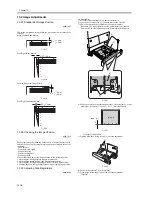
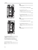
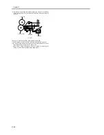
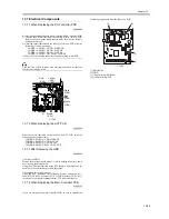
The image margin/non-image width of a print made in direct must be as
follows:
mage Leading Edge Margin
F-13-17
Left/Right Image Margin
F-13-18
Leading Edge Non-Image Width
F-13-19
Left/Right Non-Image Width
F-13-20
13.2.2 Checking the Image Position
0008-7918
Make prints using the following as the source of paper (10 prints each),
and check to see that the image margin and the non-image width are as
indicated:
- Each cassette
- Front deck (left, right)
- Manual feed tray
- Duplex feeding unit
- Side paper deck
If not as indicated, adjust the image position in the following order:
1. Adjusting the left/right image margin (registration)
2. Adjusting the image leading edge margin (registration)
3. Adjusting the left/right non-image width (CCD read start position)
4. Leading edge non-image width (scanner image leading edge position)
13.2.3 Adjusting Side Registration
0009-4593
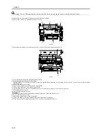
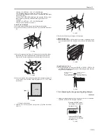
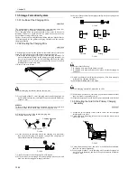
<Cassette 3/4>
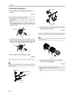
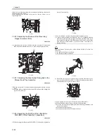
1) Press the release button to draw out the cassette 3/4.
2) Loosen the 2 fixing screws [1] on both sides of the cassette.
3) Move the cassette body frontward or backward to adjust.
Backward: The side registration value (left margin) is decreased.
Frontward: The side registration value (left margin) is increased.
F-13-21
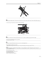
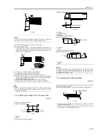
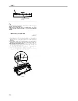
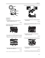
4) Make sure that the side registration values (left margins) of a copy
made from the cassette 3/4 are L1 = 2.5±1.5mm respectively.
F-13-22
[1] Paper feed direction
5) Tighten back the 2 fixing screws [1] after the adjustment.
F-13-23
6) Put back the cassette 3/4 to the machine.
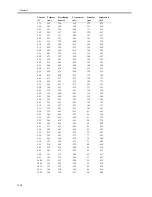
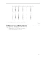
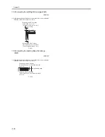
7) Perform the following service mode after the adjustment.
Cassette 3
1.5mm
1.0mm
4.0
2.5
1.5mm
0
2
4
6
8
10
1.5mm
1.0mm
4.0
2.5
1.5mm
0
2
4
6
8
10
[1]
[2]
[1]
[2]
image
L1
[1]
[1]
Summary of Contents for iR5570 Series
Page 1: ...Mar 29 2005 Service Manual iR6570 5570 Series ...
Page 2: ......
Page 6: ......
Page 26: ...Contents ...
Page 27: ...Chapter 1 Introduction ...
Page 28: ......
Page 30: ......
Page 55: ...Chapter 2 Installation ...
Page 56: ......
Page 58: ...Contents 2 9 3 Mounting the Cassette Heater 2 34 ...
Page 98: ......
Page 99: ...Chapter 3 Basic Operation ...
Page 100: ......
Page 102: ......
Page 110: ......
Page 111: ...Chapter 4 Main Controller ...
Page 112: ......
Page 114: ......
Page 135: ...Chapter 5 Original Exposure System ...
Page 136: ......
Page 181: ...Chapter 6 Laser Exposure ...
Page 182: ......
Page 184: ......
Page 192: ......
Page 193: ...Chapter 7 Image Formation ...
Page 194: ......
Page 198: ......
Page 259: ...Chapter 8 Pickup Feeding System ...
Page 260: ......
Page 350: ......
Page 351: ...Chapter 9 Fixing System ...
Page 352: ......
Page 401: ...Chapter 10 External and Controls ...
Page 402: ......
Page 406: ......
Page 448: ......
Page 449: ...Chapter 11 MEAP ...
Page 450: ......
Page 452: ......
Page 455: ...Chapter 12 Maintenance and Inspection ...
Page 456: ......
Page 458: ......
Page 468: ......
Page 469: ...Chapter 13 Standards and Adjustments ...
Page 470: ......
Page 505: ...Chapter 14 Correcting Faulty Images ...
Page 506: ......
Page 508: ......
Page 537: ...Chapter 15 Self Diagnosis ...
Page 538: ......
Page 540: ......
Page 565: ...Chapter 16 Service Mode ...
Page 566: ......
Page 568: ......
Page 633: ...Chapter 17 Upgrading ...
Page 634: ......
Page 636: ......
Page 641: ...Chapter 17 17 5 F 17 4 HDD Boot ROM Flash ROM System Software ...
Page 646: ...Chapter 17 17 10 F 17 11 8 Click START F 17 12 ...
Page 675: ...Chapter 17 17 39 F 17 59 2 Select the data to download F 17 60 3 Click Start ...
Page 677: ...Chapter 18 Service Tools ...
Page 678: ......
Page 680: ......
Page 683: ...Mar 29 2005 ...
Page 684: ......

