Chapter 9
9-21
9.4 Protective Functions
9.4.1 Detecting an Error Using the Thermistor
0009-4538
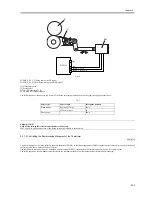
In the event of the following, the machine will set the DC power (+12 V) used to drive the AC relay (found on the fixing heater power supply PCB), thereby
stopping the AC power to the fixing heater.
- the main thermistor (TH1)/sub thermistor (TH2)/shutter thermistor (TH3) has detected overheating.
- the difference between readings of the main thermistor and the sub thermistor or between the main thermistor and the shutter thermistor has deviated from
a specific value.
9.4.2 Detecting an Error Using the Thermal Switch
0009-4540
In response to a deviation in temperature (200 +/-5 deg C), bimetal contact of the thermal switch (TP1; non-contact type) will open to cut the power supply
line (+12 VDC) used to drive the AC relay on the fixing heater power supply PCB, thereby stopping the AC power to the fixing heater.
Once open, the contact of the thermal switch will not reset itself even when the temperature drops to normal; be sure to replace the thermal switch after
removing the error.
9.4.3 Errors
0009-4626
ERROR CODE:
E000 (low temperature detection error)
0000Å@after power-on, the reading of the main thermistor is not 70 deg C or higher within 20 sec .
0010Å@the power has been turned off and then on without resetting the error in question.
E001 (abnormal rise in temperature)
0001Å@the main thermistor or the sub thermistor has been identified as being faulty, or an open circuit has been detected.
0002Å@the reading of the main thermistor or that of the sub thermistor is 230 deg C or higher for 2 sec.
0003Å@the reading is not 150 deg C or higher or 210 deg C or lower within 30 sec (at time of a remedial job).
0010Å@the power has been turned off and then on without resetting of the error in question.
E002 (faulty rise in temperature)
0000Å@the reading of the main thermistor is in excess of 70 deg C and, thereafter, it does not reach 150 deg C within 12 sec.
0001Å@the reading of the main thermistor is in excess of 100 deg C and, thereafter, it does not reach 150 deg C within 15 sec.
0010Å@the power has been turned off and then on without resetting of the error in question.
E003 (faulty rise in temperature)
0000Å@the reading of the main thermistor is in excess of 100 deg C and, thereafter, is lower than 70 deg C for 2 sec or more.
0010Å@the power has been turned off and then on without resetting of the error in question.
E004 (fixing heater power supply error (IH power supply))
0101Å@there is a mismatch between the input voltage and the IH power supply ID.
0102Å@the fault IH current is faulty (current leakage).
0103Å@the IH current is faulty (absence of current).
0104Å@there is overcurrent.
0105Å@the input voltage is too high.
0106Å@the IH input voltage is too low.
0201Å@when the power is turned on (or while the IH drive is suspended), the IH control mechanisms is not in an initial state.
0202Å@at time of IH start-up, the IH control enable flag is not set within 1 sec after the start flag has been set.
0203Å@when IH is stored, the IH control ongoing flag is not released within 1 sec.
0204Å@the 12-V power supply (IH relay) is identified as being OFF.
0205Å@at IH start-up, the PWM ON signal data has an error.
If E000 through E004 is indicated, the error code will not be reset even when you turn off the main power switch, requiring you to use service mode
(COPIER > FUNCTION > CLEAR > ERR).
Summary of Contents for iR5570 Series
Page 1: ...Mar 29 2005 Service Manual iR6570 5570 Series ...
Page 2: ......
Page 6: ......
Page 26: ...Contents ...
Page 27: ...Chapter 1 Introduction ...
Page 28: ......
Page 30: ......
Page 55: ...Chapter 2 Installation ...
Page 56: ......
Page 58: ...Contents 2 9 3 Mounting the Cassette Heater 2 34 ...
Page 98: ......
Page 99: ...Chapter 3 Basic Operation ...
Page 100: ......
Page 102: ......
Page 110: ......
Page 111: ...Chapter 4 Main Controller ...
Page 112: ......
Page 114: ......
Page 135: ...Chapter 5 Original Exposure System ...
Page 136: ......
Page 181: ...Chapter 6 Laser Exposure ...
Page 182: ......
Page 184: ......
Page 192: ......
Page 193: ...Chapter 7 Image Formation ...
Page 194: ......
Page 198: ......
Page 259: ...Chapter 8 Pickup Feeding System ...
Page 260: ......
Page 350: ......
Page 351: ...Chapter 9 Fixing System ...
Page 352: ......
Page 401: ...Chapter 10 External and Controls ...
Page 402: ......
Page 406: ......
Page 448: ......
Page 449: ...Chapter 11 MEAP ...
Page 450: ......
Page 452: ......
Page 455: ...Chapter 12 Maintenance and Inspection ...
Page 456: ......
Page 458: ......
Page 468: ......
Page 469: ...Chapter 13 Standards and Adjustments ...
Page 470: ......
Page 505: ...Chapter 14 Correcting Faulty Images ...
Page 506: ......
Page 508: ......
Page 537: ...Chapter 15 Self Diagnosis ...
Page 538: ......
Page 540: ......
Page 565: ...Chapter 16 Service Mode ...
Page 566: ......
Page 568: ......
Page 633: ...Chapter 17 Upgrading ...
Page 634: ......
Page 636: ......
Page 641: ...Chapter 17 17 5 F 17 4 HDD Boot ROM Flash ROM System Software ...
Page 646: ...Chapter 17 17 10 F 17 11 8 Click START F 17 12 ...
Page 675: ...Chapter 17 17 39 F 17 59 2 Select the data to download F 17 60 3 Click Start ...
Page 677: ...Chapter 18 Service Tools ...
Page 678: ......
Page 680: ......
Page 683: ...Mar 29 2005 ...
Page 684: ......

