Contents
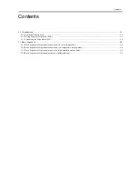
Contents
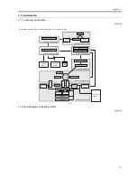
4.1 Construction ...................................................................................................................................................................4-1
4.1.1 Construction and Mechanisms ..................................................................................................................................................... 4-1
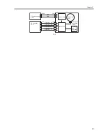
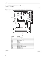
4.2 Construction of the Electrical Circuitry .........................................................................................................................4-2
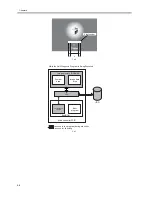
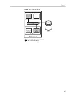
4.2.1 Main Controller PCB ................................................................................................................................................................... 4-2
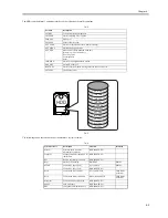
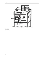
4.2.2 HDD............................................................................................................................................................................................. 4-2
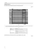
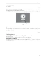
4.3 Start-Up Sequence..........................................................................................................................................................4-5
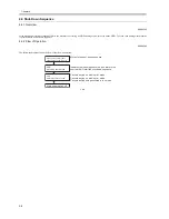
4.3.1 Overview...................................................................................................................................................................................... 4-5
4.3.2 Start-Up Sequence ....................................................................................................................................................................... 4-5
4.4 Shut-Down Sequence.....................................................................................................................................................4-8
4.4.1 Overview...................................................................................................................................................................................... 4-8
4.4.2 Flow of Operation ........................................................................................................................................................................ 4-8
4.5 Image Processing ...........................................................................................................................................................4-9
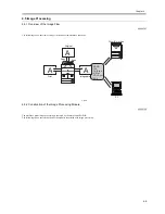
4.5.1 Overview of the Image Flow ....................................................................................................................................................... 4-9
4.5.2 Construction of the Image Processing Module............................................................................................................................ 4-9
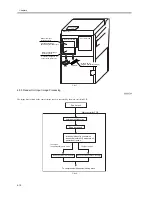
4.5.3 Reader Unit Input Image Processing ......................................................................................................................................... 4-10
4.5.4 Compression/ Extension/ Editing Block................................................................................................................................... 4-11
4.5.5 Printer unit Output Image Processing ........................................................................................................................................ 4-11
4.6 Flow of Image Data......................................................................................................................................................4-12
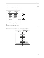
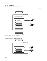
4.6.1 Flow of Image Data According to Copy Functions ................................................................................................................... 4-12
4.6.2 Flow of Image Data for the Box Function ................................................................................................................................. 4-12
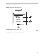
4.6.3 Flow of Image Data for the SEND Function ............................................................................................................................. 4-13
4.6.4 Flow of Image Data for the Fax Transmission .......................................................................................................................... 4-13
4.6.5 Flow of Image Data for the Fax Reception Function ................................................................................................................ 4-14
4.6.6 Flow of Image Data for the PDL Function ................................................................................................................................ 4-15
4.7 Parts Replacement Procedure.......................................................................................................................................4-16
4.7.1 Main Controller Box .................................................................................................................................................................. 4-16
4.7.1.1 Removing the Rear Cover (upper) ................................................................................................................................................................4-16
4.7.1.2 Removing the Main Controller Box..............................................................................................................................................................4-16
4.7.2 Main Controller PCB ................................................................................................................................................................. 4-17
4.7.2.1 Removing the Main Controller PCB.............................................................................................................................................................4-17
4.7.2.2 After Replacing the Main Controller PCB....................................................................................................................................................4-18
4.7.3 SDRAM ..................................................................................................................................................................................... 4-18
4.7.3.1 Removing the SDRAM .................................................................................................................................................................................4-18
4.7.4 Boot ROM.................................................................................................................................................................................. 4-18
4.7.4.1 Removing the Boot ROM .............................................................................................................................................................................4-18
4.7.5 HDD........................................................................................................................................................................................... 4-19
4.7.5.1 Removing the HDD.......................................................................................................................................................................................4-19
4.7.5.2 After Replacing the HDD..............................................................................................................................................................................4-19
4.7.6 Controller Fan ............................................................................................................................................................................ 4-19
4.7.6.1 Removing the Controller Cooling Fan..........................................................................................................................................................4-19
Summary of Contents for iR5570 Series
Page 1: ...Mar 29 2005 Service Manual iR6570 5570 Series ...
Page 2: ......
Page 6: ......
Page 26: ...Contents ...
Page 27: ...Chapter 1 Introduction ...
Page 28: ......
Page 30: ......
Page 55: ...Chapter 2 Installation ...
Page 56: ......
Page 58: ...Contents 2 9 3 Mounting the Cassette Heater 2 34 ...
Page 98: ......
Page 99: ...Chapter 3 Basic Operation ...
Page 100: ......
Page 102: ......
Page 110: ......
Page 111: ...Chapter 4 Main Controller ...
Page 112: ......
Page 114: ......
Page 135: ...Chapter 5 Original Exposure System ...
Page 136: ......
Page 181: ...Chapter 6 Laser Exposure ...
Page 182: ......
Page 184: ......
Page 192: ......
Page 193: ...Chapter 7 Image Formation ...
Page 194: ......
Page 198: ......
Page 259: ...Chapter 8 Pickup Feeding System ...
Page 260: ......
Page 350: ......
Page 351: ...Chapter 9 Fixing System ...
Page 352: ......
Page 401: ...Chapter 10 External and Controls ...
Page 402: ......
Page 406: ......
Page 448: ......
Page 449: ...Chapter 11 MEAP ...
Page 450: ......
Page 452: ......
Page 455: ...Chapter 12 Maintenance and Inspection ...
Page 456: ......
Page 458: ......
Page 468: ......
Page 469: ...Chapter 13 Standards and Adjustments ...
Page 470: ......
Page 505: ...Chapter 14 Correcting Faulty Images ...
Page 506: ......
Page 508: ......
Page 537: ...Chapter 15 Self Diagnosis ...
Page 538: ......
Page 540: ......
Page 565: ...Chapter 16 Service Mode ...
Page 566: ......
Page 568: ......
Page 633: ...Chapter 17 Upgrading ...
Page 634: ......
Page 636: ......
Page 641: ...Chapter 17 17 5 F 17 4 HDD Boot ROM Flash ROM System Software ...
Page 646: ...Chapter 17 17 10 F 17 11 8 Click START F 17 12 ...
Page 675: ...Chapter 17 17 39 F 17 59 2 Select the data to download F 17 60 3 Click Start ...
Page 677: ...Chapter 18 Service Tools ...
Page 678: ......
Page 680: ......
Page 683: ...Mar 29 2005 ...
Page 684: ......

