Chapter 3
3-4
3.2 Basic Sequence
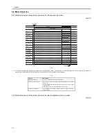
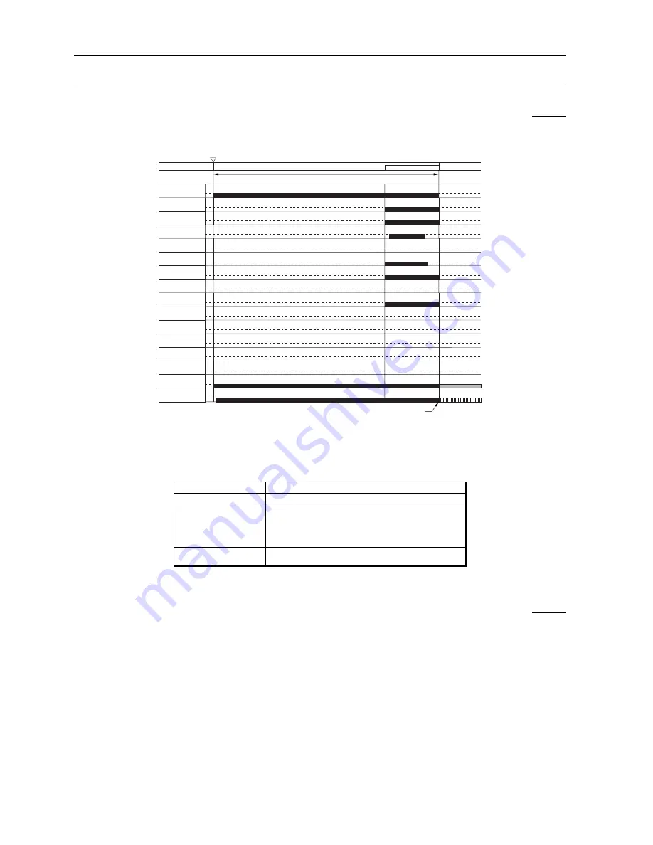
3.2.1 Basic Sequence of Operation (at power-on; 30-sec start-up mode)
0009-3720
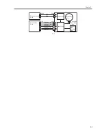
F-3-4
*1: After a shift to standby, the fixing target temperature is decreased in 5-deg C increments at specific time intervals. When a specific temperature is
reached, the fixing heater and the fixing motor are turned on and off to maintain the temperature.
T-3-2
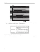
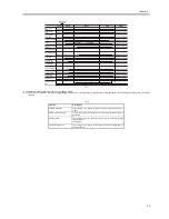
3.2.2 Basic Sequence of Operation (at power-on; low-temperature start-up mode)
0009-6336
Interval
Description
WMUPR (warm-up)
For 30 sec after the main power is turned on.
CNTR (control rotation)
The machine executes potential control for the photosensitive drum. In
the case of
30-sec start-up mode, the machine measure the potential for a single
rotation of the
drum, and adjusts only the target output. (VL control)
PSTBY (print standby)
The machine is in a state in which it is ready to accept a copy/print
request signal.
Main power
switch ON
CNTR
WMUPR
PSTBY
Main motor
(M2)
Drum motor
(M1)
Primary charging
Pre-exposure
LED (LED1)
Developing clutch
(CL1)
Developing bias
(DC)
Developing bias
(AC)
Pre-transfer
charging (DC)
Pre-transfer
charging (AC)
Separation
charging (DC)
Separation
charging (AC)
Fixing motor
(M3)
Fixing heater
(IH)
Laser
Transfer charging
Bias roller
30 sec (approx.)
205 deg C
*1
Summary of Contents for iR5570 Series
Page 1: ...Mar 29 2005 Service Manual iR6570 5570 Series ...
Page 2: ......
Page 6: ......
Page 26: ...Contents ...
Page 27: ...Chapter 1 Introduction ...
Page 28: ......
Page 30: ......
Page 55: ...Chapter 2 Installation ...
Page 56: ......
Page 58: ...Contents 2 9 3 Mounting the Cassette Heater 2 34 ...
Page 98: ......
Page 99: ...Chapter 3 Basic Operation ...
Page 100: ......
Page 102: ......
Page 110: ......
Page 111: ...Chapter 4 Main Controller ...
Page 112: ......
Page 114: ......
Page 135: ...Chapter 5 Original Exposure System ...
Page 136: ......
Page 181: ...Chapter 6 Laser Exposure ...
Page 182: ......
Page 184: ......
Page 192: ......
Page 193: ...Chapter 7 Image Formation ...
Page 194: ......
Page 198: ......
Page 259: ...Chapter 8 Pickup Feeding System ...
Page 260: ......
Page 350: ......
Page 351: ...Chapter 9 Fixing System ...
Page 352: ......
Page 401: ...Chapter 10 External and Controls ...
Page 402: ......
Page 406: ......
Page 448: ......
Page 449: ...Chapter 11 MEAP ...
Page 450: ......
Page 452: ......
Page 455: ...Chapter 12 Maintenance and Inspection ...
Page 456: ......
Page 458: ......
Page 468: ......
Page 469: ...Chapter 13 Standards and Adjustments ...
Page 470: ......
Page 505: ...Chapter 14 Correcting Faulty Images ...
Page 506: ......
Page 508: ......
Page 537: ...Chapter 15 Self Diagnosis ...
Page 538: ......
Page 540: ......
Page 565: ...Chapter 16 Service Mode ...
Page 566: ......
Page 568: ......
Page 633: ...Chapter 17 Upgrading ...
Page 634: ......
Page 636: ......
Page 641: ...Chapter 17 17 5 F 17 4 HDD Boot ROM Flash ROM System Software ...
Page 646: ...Chapter 17 17 10 F 17 11 8 Click START F 17 12 ...
Page 675: ...Chapter 17 17 39 F 17 59 2 Select the data to download F 17 60 3 Click Start ...
Page 677: ...Chapter 18 Service Tools ...
Page 678: ......
Page 680: ......
Page 683: ...Mar 29 2005 ...
Page 684: ......

