Chapter 16
16-13
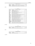
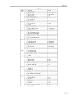
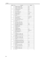
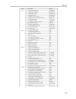
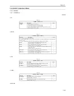
T-16-12
Address
bit
Description
Remarks
P001
0
delivery motor CLK
1
DDIS IF (OPT00-)
0: prohibit operation
2
DDIS IF (SPRDY)
0: permit operation
3
DDIS IF (OPTI0)
0: active
4
ADF pickup motor CLK
5
fan power supply ON signal
1: ON
6
ADF read motor CLK
7
size sensor ON
1: ON
P002
0
shift motor CLK
1
24V power monitor
0: normal
2-3
not used
4
scanner motor CLK
5
13V power supply monitor
0: normal
6
Canon Electronics switchover
0: Canon Electronics
7
DDIS IF (SCPRDY)
0: permit operation
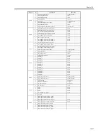
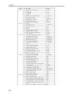
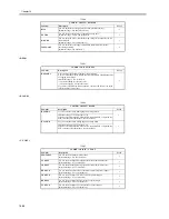
P003
0
DDIS serial communication (TxD)
1
ADF serial communication (TxD)
2
DDIS serial communication (RxD)
3
ADF serial communication (RxD)
4
LED control
1: ON
5
ADF serial communication (SCK)
6-7
not used
P004
0
original size detection 0
0: original present
1
original size detection 1
0: original present
2
original size detection 2
0: original present
3
original size detection 3
0: original present
4
DF connection detection
5
DDIS IF (SRTS)
0: permit reception
6
scanner motor Vref output
7
not used
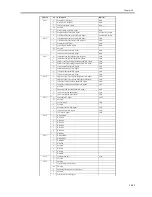
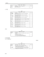
P005
0
PC connection IF (TxD)
1
PC connection IF (RxD)
2
fan lock detection signal
0: enable
3
DDIS IF (SCTS)
0: permit reception
4-7
not used
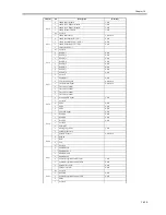
P006
0
not used
1
PCB check terminal
1: normal
2
DDIS IF (OPTI1)
0: active
3
DDIS IF (OPTO1)
0: active
4
ADF sensor interrupt input
0: active
5
platen cover open/closed sensor interrupt input 0
1: cover open
6
HP sensor interrupt input
1: HP
7
not used
P007
0
address bus 16
1
address bus 17
2
address bus 18
3-4
not used
5
ADF pickup motor clock interrupt input
6
ADF read motor clock interrupt input
7
ADF reversal motor clock interrupt input
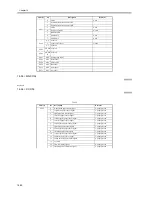
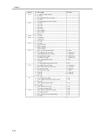
P008
0
lamp ON signal
1: ON
1
CCD drive ON signal
1: ON
2
wait signal
0: wait
3
L light signal
0: active
4
H light signal
0: active
5
read signal
0: active
6
ADF serial communication (LOAD)
0: enable
7
CPU click output
Summary of Contents for iR5570 Series
Page 1: ...Mar 29 2005 Service Manual iR6570 5570 Series ...
Page 2: ......
Page 6: ......
Page 26: ...Contents ...
Page 27: ...Chapter 1 Introduction ...
Page 28: ......
Page 30: ......
Page 55: ...Chapter 2 Installation ...
Page 56: ......
Page 58: ...Contents 2 9 3 Mounting the Cassette Heater 2 34 ...
Page 98: ......
Page 99: ...Chapter 3 Basic Operation ...
Page 100: ......
Page 102: ......
Page 110: ......
Page 111: ...Chapter 4 Main Controller ...
Page 112: ......
Page 114: ......
Page 135: ...Chapter 5 Original Exposure System ...
Page 136: ......
Page 181: ...Chapter 6 Laser Exposure ...
Page 182: ......
Page 184: ......
Page 192: ......
Page 193: ...Chapter 7 Image Formation ...
Page 194: ......
Page 198: ......
Page 259: ...Chapter 8 Pickup Feeding System ...
Page 260: ......
Page 350: ......
Page 351: ...Chapter 9 Fixing System ...
Page 352: ......
Page 401: ...Chapter 10 External and Controls ...
Page 402: ......
Page 406: ......
Page 448: ......
Page 449: ...Chapter 11 MEAP ...
Page 450: ......
Page 452: ......
Page 455: ...Chapter 12 Maintenance and Inspection ...
Page 456: ......
Page 458: ......
Page 468: ......
Page 469: ...Chapter 13 Standards and Adjustments ...
Page 470: ......
Page 505: ...Chapter 14 Correcting Faulty Images ...
Page 506: ......
Page 508: ......
Page 537: ...Chapter 15 Self Diagnosis ...
Page 538: ......
Page 540: ......
Page 565: ...Chapter 16 Service Mode ...
Page 566: ......
Page 568: ......
Page 633: ...Chapter 17 Upgrading ...
Page 634: ......
Page 636: ......
Page 641: ...Chapter 17 17 5 F 17 4 HDD Boot ROM Flash ROM System Software ...
Page 646: ...Chapter 17 17 10 F 17 11 8 Click START F 17 12 ...
Page 675: ...Chapter 17 17 39 F 17 59 2 Select the data to download F 17 60 3 Click Start ...
Page 677: ...Chapter 18 Service Tools ...
Page 678: ......
Page 680: ......
Page 683: ...Mar 29 2005 ...
Page 684: ......

