Chapter 16
16-32
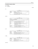
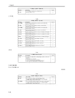
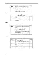
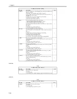
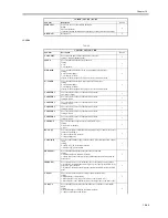
<CLEANING>
T-16-37
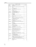
<FIXING>
T-16-38
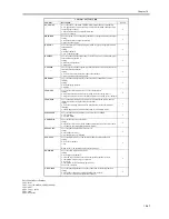
<PANEL>
T-16-39
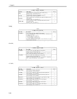
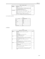
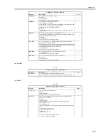
MF-A4R
MF-A6R
MF-A4
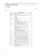
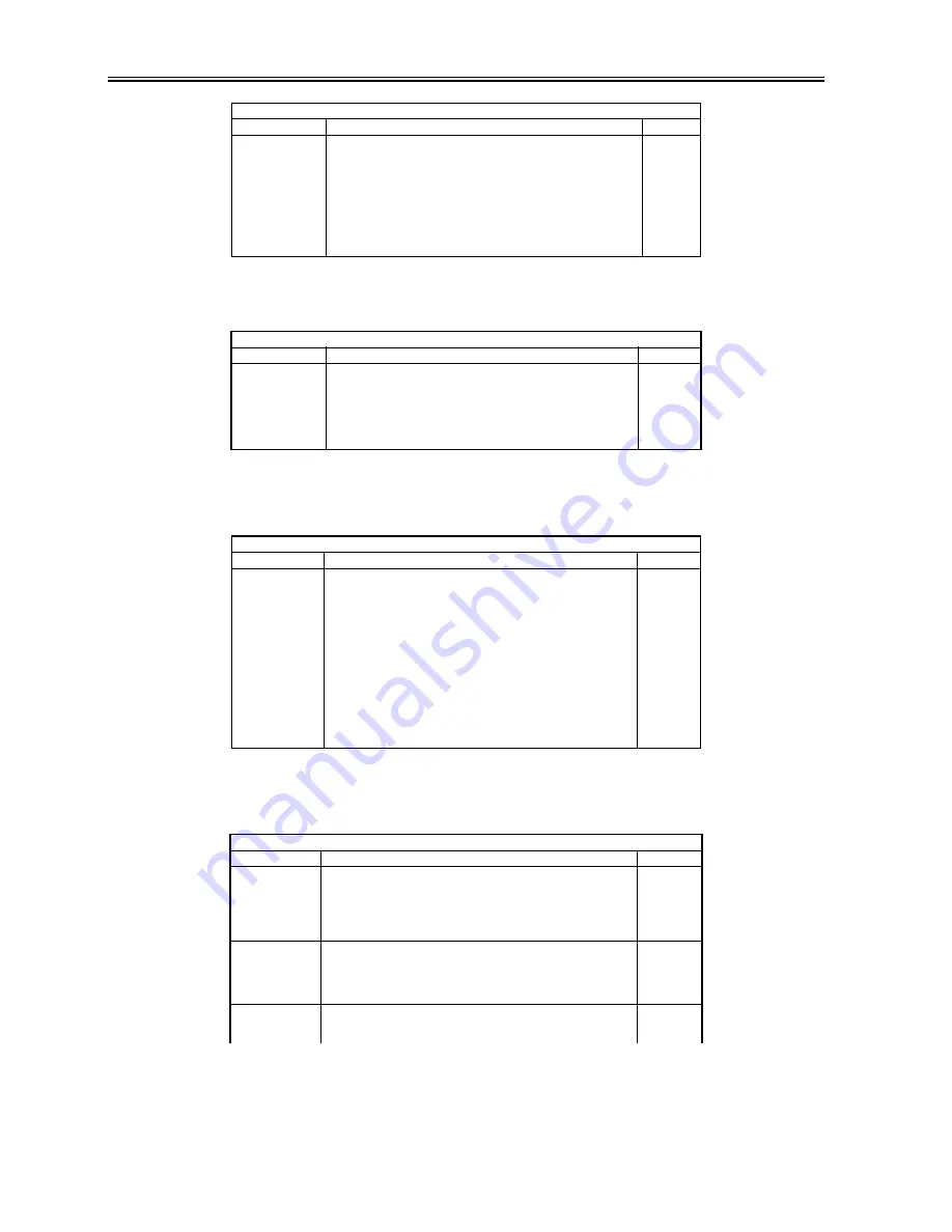
Use it to register the paper width basic value for the manual feed tray.
A4R width: 210 mm; A6R: 105 mm; A4 width: 297 mm
To make fine adjustments after registering a basic value, use the following:
COPIER>ADJUST>CST-ADJ>MF-A4R, MF-A6R, MF-A4.
Procedure
1) Put A4R paper in the manual feed tray, and adjust the size guide to the
width.
2) Select MF-A4R to highlight, and press the OK key so that the machine
executes auto adjustment and register the value.
3) Likewise, repeat steps 1) and 2) for A6R and A4.
1
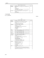
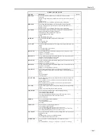
COPIER > FUNCTION > CLEANING
Sub-item
Description
Level
WIRE-CLN
Clean all charging wires 5 times (5 trips) all at the same time.
Procedure
1) Select the item to highlight, and press the OK key.
2) See that the notation changes to 'ACTIVE', indicating that the charging
wires are being cleaned.
3) See that the machine stops cleaning automatically. (To stop in the middle,
press the OK key.)
1
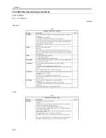
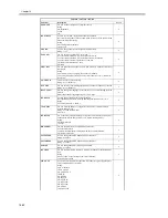
COPIER > FUNCTION > FIXING
Sub-item
Description
Level
NIP-CHK
Use it to generate printouts for automatic measurement of the fixing nip
width.
Procedure
1) Make about 20 A4 prints.
2) Put A4 plain or recycled paper in the manual feed tray.
3) Select the item to highlight, and press the OK key.
4) See that the paper is picked from the manual feed tray, held in the fixing
nip area, and discharged in about 20 sec.
5) Check the nip width of the discharged paper: if b is from 4.5 to 6.5 mm,
the nip may be considered normal. In the event of a fixing fault or wrinkling
and if the difference between the front b and the rear c is appreciable, go to
step 6) to make adjustments.
6) Loosen the screw found on the side with the narrower nip; then, tighten
the other screw to the same degree (so that the nip width is identical between
front and rear).
1
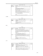
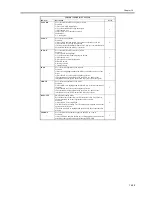
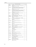
COPIER > FUNCTION > PANEL
Sub-item
Description
Level
LCD-CHK
Use it to check for missing dots in the LCD.
Procedure
1) Select the item, and press the OK key to start. See that the front of the
touch panel starts to go on in the following order: white, black, red, green,
blue.
2) Press the Stop key to end the operation.
1
LED-CHK
Use it to check the activation of the LEDs on the control panel.
Procedure
1) Select the item, an press the OK key to start. See that the LEDs go on in
sequence.
2) Press [LED-off] to end the operation.
1
LED-OFF
Check the LEDs on the control panel.
Procedure
1) Select the item to end the operation for LED-CHK.
1
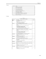
COPIER > FUNCTION > CST
Sub-item
Description
Level
Summary of Contents for iR5570 Series
Page 1: ...Mar 29 2005 Service Manual iR6570 5570 Series ...
Page 2: ......
Page 6: ......
Page 26: ...Contents ...
Page 27: ...Chapter 1 Introduction ...
Page 28: ......
Page 30: ......
Page 55: ...Chapter 2 Installation ...
Page 56: ......
Page 58: ...Contents 2 9 3 Mounting the Cassette Heater 2 34 ...
Page 98: ......
Page 99: ...Chapter 3 Basic Operation ...
Page 100: ......
Page 102: ......
Page 110: ......
Page 111: ...Chapter 4 Main Controller ...
Page 112: ......
Page 114: ......
Page 135: ...Chapter 5 Original Exposure System ...
Page 136: ......
Page 181: ...Chapter 6 Laser Exposure ...
Page 182: ......
Page 184: ......
Page 192: ......
Page 193: ...Chapter 7 Image Formation ...
Page 194: ......
Page 198: ......
Page 259: ...Chapter 8 Pickup Feeding System ...
Page 260: ......
Page 350: ......
Page 351: ...Chapter 9 Fixing System ...
Page 352: ......
Page 401: ...Chapter 10 External and Controls ...
Page 402: ......
Page 406: ......
Page 448: ......
Page 449: ...Chapter 11 MEAP ...
Page 450: ......
Page 452: ......
Page 455: ...Chapter 12 Maintenance and Inspection ...
Page 456: ......
Page 458: ......
Page 468: ......
Page 469: ...Chapter 13 Standards and Adjustments ...
Page 470: ......
Page 505: ...Chapter 14 Correcting Faulty Images ...
Page 506: ......
Page 508: ......
Page 537: ...Chapter 15 Self Diagnosis ...
Page 538: ......
Page 540: ......
Page 565: ...Chapter 16 Service Mode ...
Page 566: ......
Page 568: ......
Page 633: ...Chapter 17 Upgrading ...
Page 634: ......
Page 636: ......
Page 641: ...Chapter 17 17 5 F 17 4 HDD Boot ROM Flash ROM System Software ...
Page 646: ...Chapter 17 17 10 F 17 11 8 Click START F 17 12 ...
Page 675: ...Chapter 17 17 39 F 17 59 2 Select the data to download F 17 60 3 Click Start ...
Page 677: ...Chapter 18 Service Tools ...
Page 678: ......
Page 680: ......
Page 683: ...Mar 29 2005 ...
Page 684: ......


