Chapter 5
5-12
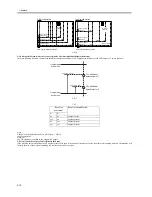
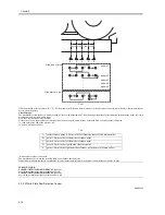
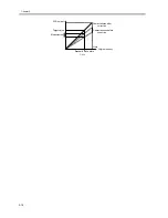
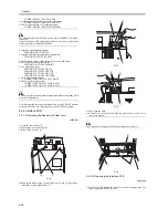
F-5-20
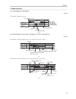
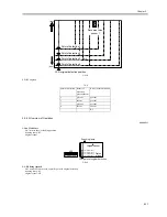
3. ADF Being Closed
No. 1 mirror base: at point of original detection
scanning lamp: off -> on
original sensor: original detection operation
- When the ADF is at 25 deg or lower, the external light within the width of any original is kept out of external light, thus causing the machine to assume
the absence of an original at points of external light detection (external light search operation).
The ADF open/closed sensor 2 identifies the state as being "closed," and the machine starts original size detection.
Here, B5, B4, A4, and A3 are eliminated from the list of possible sizes.
- When the external light search is over, the machine turns on the xenon lamp for the main scanning lamp, and checks the CCD (4 points) for external light.
For sub scanning direction, the machine starts to operate the original sensor.
F-5-21
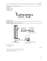
F-5-22
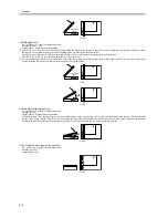
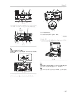
4. ADF Fully Closed (5 deg or less)
No. 1 mirror base: at point of original detection
scanning lamp: on
original sensor: original detection operation
The machine looks for a change in the output level of individual sensors for a period of 2 sec after the ADF open/closed sensor 1 has identified the
current state as being "closed." The absence of a change in the level causes the machine to assume the presence of an original at the point in question.
The machine uses the combination of changes in the levels of 5 points to identify the size of the original in question.
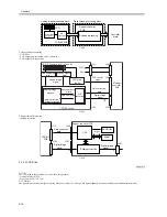
F-5-23
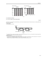
5. In a Wait State (for a press on the Start key)
No.1 mirror base: at point of original detection
scanning lamp: off
original sensor: off
F-5-24
(external
light)
(external
light)
25
5
Summary of Contents for iR5570 Series
Page 1: ...Mar 29 2005 Service Manual iR6570 5570 Series ...
Page 2: ......
Page 6: ......
Page 26: ...Contents ...
Page 27: ...Chapter 1 Introduction ...
Page 28: ......
Page 30: ......
Page 55: ...Chapter 2 Installation ...
Page 56: ......
Page 58: ...Contents 2 9 3 Mounting the Cassette Heater 2 34 ...
Page 98: ......
Page 99: ...Chapter 3 Basic Operation ...
Page 100: ......
Page 102: ......
Page 110: ......
Page 111: ...Chapter 4 Main Controller ...
Page 112: ......
Page 114: ......
Page 135: ...Chapter 5 Original Exposure System ...
Page 136: ......
Page 181: ...Chapter 6 Laser Exposure ...
Page 182: ......
Page 184: ......
Page 192: ......
Page 193: ...Chapter 7 Image Formation ...
Page 194: ......
Page 198: ......
Page 259: ...Chapter 8 Pickup Feeding System ...
Page 260: ......
Page 350: ......
Page 351: ...Chapter 9 Fixing System ...
Page 352: ......
Page 401: ...Chapter 10 External and Controls ...
Page 402: ......
Page 406: ......
Page 448: ......
Page 449: ...Chapter 11 MEAP ...
Page 450: ......
Page 452: ......
Page 455: ...Chapter 12 Maintenance and Inspection ...
Page 456: ......
Page 458: ......
Page 468: ......
Page 469: ...Chapter 13 Standards and Adjustments ...
Page 470: ......
Page 505: ...Chapter 14 Correcting Faulty Images ...
Page 506: ......
Page 508: ......
Page 537: ...Chapter 15 Self Diagnosis ...
Page 538: ......
Page 540: ......
Page 565: ...Chapter 16 Service Mode ...
Page 566: ......
Page 568: ......
Page 633: ...Chapter 17 Upgrading ...
Page 634: ......
Page 636: ......
Page 641: ...Chapter 17 17 5 F 17 4 HDD Boot ROM Flash ROM System Software ...
Page 646: ...Chapter 17 17 10 F 17 11 8 Click START F 17 12 ...
Page 675: ...Chapter 17 17 39 F 17 59 2 Select the data to download F 17 60 3 Click Start ...
Page 677: ...Chapter 18 Service Tools ...
Page 678: ......
Page 680: ......
Page 683: ...Mar 29 2005 ...
Page 684: ......


