Chapter 17
17-9
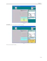
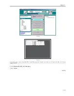
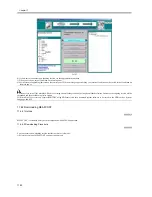
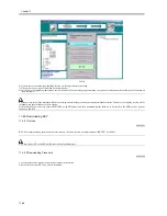
F-17-9
3) Check to see that the Execute/Memory lamp on the control panel is off, and turn off the main power switch.
3-1) Hold down the power switch on the control panel for 3 sec or more.
3-2) Follow the instructions indicated on the control panel so that the main power switch may be turned off.
3-3) Turn off the main power switch.
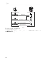
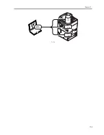
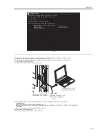
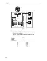
4) Connect the PC to the machine using a cross cable.
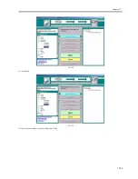
F-17-10
5) Start up the machine to suit the download mode you will be using (iR4570/3570, 2870/2270 Series).
- Normal Mode
Turn on the main power switch while holding down 1+7.
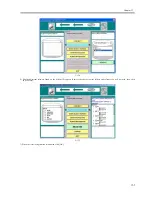
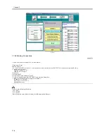
When the machine has started up, make the following selections: COPIER > FUNCTION > SYSTEM > DOWNLOAD.
- Safe Mode
Turn on the main power switch while holding down 2+8.
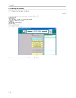
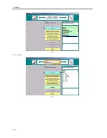
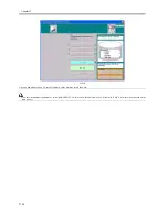
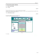
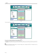
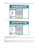
6) Start up the Service Support Tool.
7) Select the model of the machine to connect (iR5570).
C:
\
W i n d o w s 2 0 0 0 I P C o n f i g u r a t i o n
M i c r o s o f t W i n d o w s 2 0 0 0 [ Ve r s i o n 5 . 0 0 . 2 1 9 5 ]
( C ) C o p y r i g h t 1 9 8 5 - 1 9 9 9 M i n c r o s o f t C o r p .
E t h e r n e t a d a p t e r L o c a l A r e a C o n n e c t i o n :
C o n n e c t i o n - s p e c i f i c D N S S u f f i x . :
I P A d d r e s s . . . . . . . . . . . . : 1 7 2 . 1 6 . 1 . 1 6 0
S u b n e t M a s k . . . . . . . . . . . : 2 5 5 . 2 5 5 . 2 5 5 . 0
D e f a u l t G a t e w a y . . . . . . . . . :
C : \
C : \ i p c o n f i g
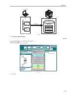
Command Prompt
IP address: 172.16.1.100
Subnet mask: 255.255.255.0
IP sddress: 172.16.1.160
Subnet mask: 255.255.255.0
Cross cable
10Base-T: category 3 or 5
100Base-TX: category 5
Summary of Contents for iR5570 Series
Page 1: ...Mar 29 2005 Service Manual iR6570 5570 Series ...
Page 2: ......
Page 6: ......
Page 26: ...Contents ...
Page 27: ...Chapter 1 Introduction ...
Page 28: ......
Page 30: ......
Page 55: ...Chapter 2 Installation ...
Page 56: ......
Page 58: ...Contents 2 9 3 Mounting the Cassette Heater 2 34 ...
Page 98: ......
Page 99: ...Chapter 3 Basic Operation ...
Page 100: ......
Page 102: ......
Page 110: ......
Page 111: ...Chapter 4 Main Controller ...
Page 112: ......
Page 114: ......
Page 135: ...Chapter 5 Original Exposure System ...
Page 136: ......
Page 181: ...Chapter 6 Laser Exposure ...
Page 182: ......
Page 184: ......
Page 192: ......
Page 193: ...Chapter 7 Image Formation ...
Page 194: ......
Page 198: ......
Page 259: ...Chapter 8 Pickup Feeding System ...
Page 260: ......
Page 350: ......
Page 351: ...Chapter 9 Fixing System ...
Page 352: ......
Page 401: ...Chapter 10 External and Controls ...
Page 402: ......
Page 406: ......
Page 448: ......
Page 449: ...Chapter 11 MEAP ...
Page 450: ......
Page 452: ......
Page 455: ...Chapter 12 Maintenance and Inspection ...
Page 456: ......
Page 458: ......
Page 468: ......
Page 469: ...Chapter 13 Standards and Adjustments ...
Page 470: ......
Page 505: ...Chapter 14 Correcting Faulty Images ...
Page 506: ......
Page 508: ......
Page 537: ...Chapter 15 Self Diagnosis ...
Page 538: ......
Page 540: ......
Page 565: ...Chapter 16 Service Mode ...
Page 566: ......
Page 568: ......
Page 633: ...Chapter 17 Upgrading ...
Page 634: ......
Page 636: ......
Page 641: ...Chapter 17 17 5 F 17 4 HDD Boot ROM Flash ROM System Software ...
Page 646: ...Chapter 17 17 10 F 17 11 8 Click START F 17 12 ...
Page 675: ...Chapter 17 17 39 F 17 59 2 Select the data to download F 17 60 3 Click Start ...
Page 677: ...Chapter 18 Service Tools ...
Page 678: ......
Page 680: ......
Page 683: ...Mar 29 2005 ...
Page 684: ......

