Chapter 7
7-9
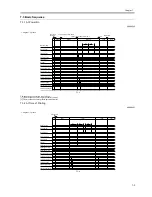
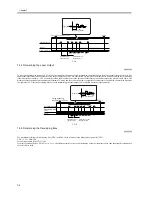
F-7-11
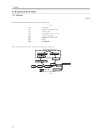
7.4.6 APC Correction
0009-3545
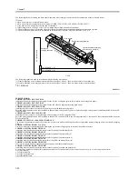
Changes in the laser output cause changes in the surface potential. To maintain a specific level of surface potential, the machine corrects the laser output
control value. The following shows the type and the particulars of laser output control value correction:
1. Between-Sheet APC Control
Purpose: to maintain a specific level of surface potential without lowering the productivity during a continuous job; the machine measures the potential
after laser output between sheets, and corrects the laser output control value.
Timing: over the 1st interval between sheets every 1 min after the start of a continuous print job.
Potential measurement: the drum potential varies in drum peripheral direction; thus, the machine computes the average drum surface potential in drum
peripheral direction. It uses the result of computation to determine the laser output correction value. If measurement is not possible because of conditions
imposed by the need for measurement between sheets, the machine will continue measurement for an additional 1 min.
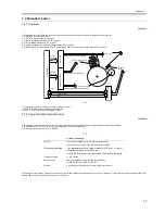
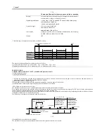
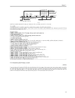
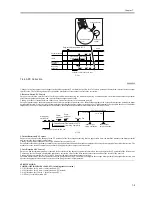
F-7-12
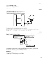
2. Initial Rotation APC Control
Purpose: to make up for the changes in the VL potential of the laser output occurring after an appreciable time, the machine measures the drum potential
and corrects the laser output control value.
Timing: during initial rotation of the 1st job 60 min after the end of a job.
Potential measurement: the drum potential varies in peripheral direction, and the machine computes the average drum potential in peripheral direction. The
machine uses the result of computation to obtain the appropriate laser output correction value.
3. Last Rotation APC Control
Purpose: when intermittent printing is repeated at short intervals, the absence of potential control can cause changes in the VL potential of the laser output.
To make up for the changes, the machine computes a correction value for the laser output control value and uses the result for the next job.
Timing: during last rotation for the 1st job 30 min after the most recent laser output correction.
Potential measurement: the drum potential varies in peripheral direction. The machine computes the average drum potential in peripheral direction, and
obtains the appropriate laser output correction value using the result of computation.
SERVICE MODE:
COPIER>OPTION>BODY>LAPS-SW (switching laser correction)
0: ON (left alone for 10 min -> initial rotation APC)
1: ON (left alone for 60 min -> initial rotation APC; default)
2: ON (left alone for 120 min -> initial rotation APC)
3: OFF only for initial rotation APC
WMUPR
WMUP
STBY
200 C
Potential sensor
Resulting
potential
Laser
Secondary
charging
VpcVpc
LP0
Vpc
Potential control sequence start
VD
VL1
VL2
Vdc
VD
Vdc
Photosensitive
drum
Developing
cylinder
Potential sensor
Laser output
determined
Fixing assembly temperature 195 C
LP
Primary charging
current determined
Copier
potential
control
Printer
potential
control
Main power
switch ON
Fixing assembly temperature 195- C
(fixing assembly warm-up complete)
Control panel power switch ON
Start key ON
laser output
value correction
1 min later
1 min later
Continuous printing
Laser output
value correction
Summary of Contents for iR5570 Series
Page 1: ...Mar 29 2005 Service Manual iR6570 5570 Series ...
Page 2: ......
Page 6: ......
Page 26: ...Contents ...
Page 27: ...Chapter 1 Introduction ...
Page 28: ......
Page 30: ......
Page 55: ...Chapter 2 Installation ...
Page 56: ......
Page 58: ...Contents 2 9 3 Mounting the Cassette Heater 2 34 ...
Page 98: ......
Page 99: ...Chapter 3 Basic Operation ...
Page 100: ......
Page 102: ......
Page 110: ......
Page 111: ...Chapter 4 Main Controller ...
Page 112: ......
Page 114: ......
Page 135: ...Chapter 5 Original Exposure System ...
Page 136: ......
Page 181: ...Chapter 6 Laser Exposure ...
Page 182: ......
Page 184: ......
Page 192: ......
Page 193: ...Chapter 7 Image Formation ...
Page 194: ......
Page 198: ......
Page 259: ...Chapter 8 Pickup Feeding System ...
Page 260: ......
Page 350: ......
Page 351: ...Chapter 9 Fixing System ...
Page 352: ......
Page 401: ...Chapter 10 External and Controls ...
Page 402: ......
Page 406: ......
Page 448: ......
Page 449: ...Chapter 11 MEAP ...
Page 450: ......
Page 452: ......
Page 455: ...Chapter 12 Maintenance and Inspection ...
Page 456: ......
Page 458: ......
Page 468: ......
Page 469: ...Chapter 13 Standards and Adjustments ...
Page 470: ......
Page 505: ...Chapter 14 Correcting Faulty Images ...
Page 506: ......
Page 508: ......
Page 537: ...Chapter 15 Self Diagnosis ...
Page 538: ......
Page 540: ......
Page 565: ...Chapter 16 Service Mode ...
Page 566: ......
Page 568: ......
Page 633: ...Chapter 17 Upgrading ...
Page 634: ......
Page 636: ......
Page 641: ...Chapter 17 17 5 F 17 4 HDD Boot ROM Flash ROM System Software ...
Page 646: ...Chapter 17 17 10 F 17 11 8 Click START F 17 12 ...
Page 675: ...Chapter 17 17 39 F 17 59 2 Select the data to download F 17 60 3 Click Start ...
Page 677: ...Chapter 18 Service Tools ...
Page 678: ......
Page 680: ......
Page 683: ...Mar 29 2005 ...
Page 684: ......


