Chapter 16
16-25
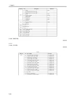
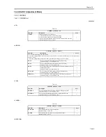
16.4 ADJUST (Adjustment Mode)
16.4.1 COPIER
16.4.1.1 COPIER List
0009-6069
<AE>
T-16-16
<ADJ-XY>
T-16-17
<CCD>
T-16-18
<LASER>
T-16-19
<DEVELOP>
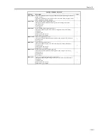
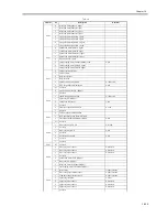
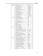
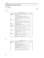
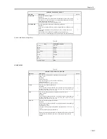
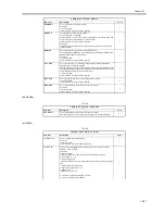
COPIER > ADJUST > AE
Sub-item
Description
Level
AE-TBL
adjustment range: 1 to 9 (default: 5)
- to obtain darker characters, increase the setting.
- to obtain lighter characters, decrease the setting.
If you have initialized the RAM on the reader controller PCB, enter the
value indicated on the service label.
1
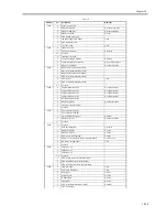
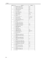
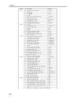
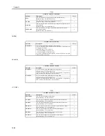
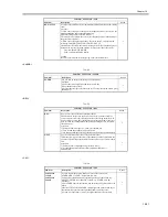
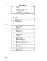
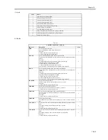
COPIER > ADJUST > ADJ-XY
Sub-item
Description
Level
Use it to adjust the image read start position.
- If you have initialized the RAM on the reader controller PCB or replaced the PCB, enter the value indicated on
the service label.
- If you have changed the setting of this item, record the new setting on the service label.
ADJ-X
Use it to adjust the image read start position (X direction).
adjustment range: 1 to 100 (default: 20)
1
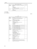
ADJ-Y
Use it to adjust the image read start position (Y direction).
adjustment range: 47 to 131 (default: 90)
1
ADJ-S
Use it to adjust the point at which data is collected for shading using the
standard white plate.
adjustment range: 20 to 200 (default: 50)
1
ADJ-Y-DF
Use it to adjust the main scanning position for feeder mode.
adjustment range: 21 to 106 (default: 53)
1
STRD_POS
Use it to adjust the CCD read position for DF stream reading mode.
adjustment range: 1 to 200 (default: 100)
1
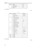
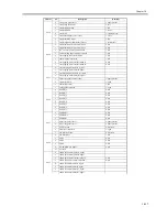
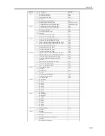
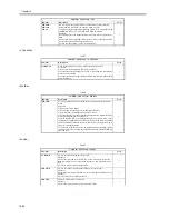
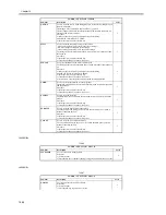
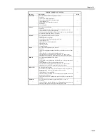
COPIER > ADJUST > CCD
Sub-item
Description
Level
SH-TRGT
Use it to enter the white level target value for shading correction.
adjustment range: 1 to 2047 (default: 1136)
1
DFTAR-G
Use it to adjust the shading target value for green for DF mode.
adjustment range: 1 to 2047 (default: 1189)
1
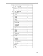
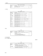
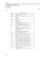
COPIER > ADJUST > LASER
Sub-item
Description
Level
PVE-OFST
Use it to adjust the laser write start position.
adjustment range: -300 to 300
1
POWER
Use it to adjust the laser power (for non-potential control).
adjustment range: 0 to 255
1
Summary of Contents for iR5570 Series
Page 1: ...Mar 29 2005 Service Manual iR6570 5570 Series ...
Page 2: ......
Page 6: ......
Page 26: ...Contents ...
Page 27: ...Chapter 1 Introduction ...
Page 28: ......
Page 30: ......
Page 55: ...Chapter 2 Installation ...
Page 56: ......
Page 58: ...Contents 2 9 3 Mounting the Cassette Heater 2 34 ...
Page 98: ......
Page 99: ...Chapter 3 Basic Operation ...
Page 100: ......
Page 102: ......
Page 110: ......
Page 111: ...Chapter 4 Main Controller ...
Page 112: ......
Page 114: ......
Page 135: ...Chapter 5 Original Exposure System ...
Page 136: ......
Page 181: ...Chapter 6 Laser Exposure ...
Page 182: ......
Page 184: ......
Page 192: ......
Page 193: ...Chapter 7 Image Formation ...
Page 194: ......
Page 198: ......
Page 259: ...Chapter 8 Pickup Feeding System ...
Page 260: ......
Page 350: ......
Page 351: ...Chapter 9 Fixing System ...
Page 352: ......
Page 401: ...Chapter 10 External and Controls ...
Page 402: ......
Page 406: ......
Page 448: ......
Page 449: ...Chapter 11 MEAP ...
Page 450: ......
Page 452: ......
Page 455: ...Chapter 12 Maintenance and Inspection ...
Page 456: ......
Page 458: ......
Page 468: ......
Page 469: ...Chapter 13 Standards and Adjustments ...
Page 470: ......
Page 505: ...Chapter 14 Correcting Faulty Images ...
Page 506: ......
Page 508: ......
Page 537: ...Chapter 15 Self Diagnosis ...
Page 538: ......
Page 540: ......
Page 565: ...Chapter 16 Service Mode ...
Page 566: ......
Page 568: ......
Page 633: ...Chapter 17 Upgrading ...
Page 634: ......
Page 636: ......
Page 641: ...Chapter 17 17 5 F 17 4 HDD Boot ROM Flash ROM System Software ...
Page 646: ...Chapter 17 17 10 F 17 11 8 Click START F 17 12 ...
Page 675: ...Chapter 17 17 39 F 17 59 2 Select the data to download F 17 60 3 Click Start ...
Page 677: ...Chapter 18 Service Tools ...
Page 678: ......
Page 680: ......
Page 683: ...Mar 29 2005 ...
Page 684: ......

