Chapter 12
12-1
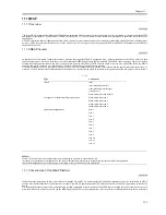
12.1 Periodically Replaced Parts
12.1.1 Outline
0009-5822
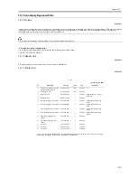
Some parts of the machine must be replaced on a periodical basis for the machine to maintain a specific level of performance. They must be replaced
regardless of the presence/absence of external changes or damage, as the performance of the machine will be considerably affected once they fail.
If possible, plan any replacement to coincide with a scheduled visit.
The intervals indicated may vary depending on the site environment and user habit.
- Checking the Timing of Replacement
The timing of replacement may be checked using the following service mode items:
COPIER > COUNTER > PRDC-1
12.1.2 Reader Unit
0009-5823
The reader unit does not have parts that require periodical replacement.
12.1.3 Printer Unit
0009-5824
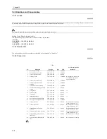
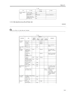
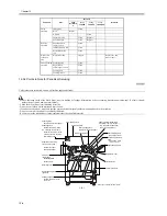
T-12-1
As of December 2004
No.
Part name
Part No.
Q'ty
Life
Remarks
1
Primary, pre-transfer, transfer,
separation charging wire
FB4-3687-000
AR
500,000
(*)
2
Primary grid wire
FY1-0883-000
AR
500,000
3
thermistor unit
FK2-0809-000
1
500,000
Main ther shutter
thermister
4
Sub thermistor
FM2-4161-000
1
500,000
5
Primary charging wire cleaner 1 FF5-6883-000
2
500,000
Strengthened polish type
(blue)
6
Primary charging wire cleaner 2 FF5-6884-000
2
500,000
Strengthened polish type
(blue)
7
Transfer charging wire cleaner 1 FF5-6883-000
1
500,000
Strengthened polish type
(blue)
8
Transfer charging wire cleaner 2 FF5-6884-000
1
500,000
Strengthened polish type
(blue)
9
Separation charging wire
cleaner
FF5-3090-000
2
500,000
10
Pre-transfer charging wire
cleaner
FF5-3090-000
1
500,000
11
Air filter 1
FC6-3482-000
1
500,000
12
Air filter 2
FC6-3483-000
1
500,000
13
Ozone filter
FC6-3693-000
1
500,000
*: Do not use the old type (gold plated). After replacement of the charge wire, be sure to execute wire cleaning in
service mode. (COPIER > FUNCTION > CLEANING > WIRECLN)
Summary of Contents for iR5570 Series
Page 1: ...Mar 29 2005 Service Manual iR6570 5570 Series ...
Page 2: ......
Page 6: ......
Page 26: ...Contents ...
Page 27: ...Chapter 1 Introduction ...
Page 28: ......
Page 30: ......
Page 55: ...Chapter 2 Installation ...
Page 56: ......
Page 58: ...Contents 2 9 3 Mounting the Cassette Heater 2 34 ...
Page 98: ......
Page 99: ...Chapter 3 Basic Operation ...
Page 100: ......
Page 102: ......
Page 110: ......
Page 111: ...Chapter 4 Main Controller ...
Page 112: ......
Page 114: ......
Page 135: ...Chapter 5 Original Exposure System ...
Page 136: ......
Page 181: ...Chapter 6 Laser Exposure ...
Page 182: ......
Page 184: ......
Page 192: ......
Page 193: ...Chapter 7 Image Formation ...
Page 194: ......
Page 198: ......
Page 259: ...Chapter 8 Pickup Feeding System ...
Page 260: ......
Page 350: ......
Page 351: ...Chapter 9 Fixing System ...
Page 352: ......
Page 401: ...Chapter 10 External and Controls ...
Page 402: ......
Page 406: ......
Page 448: ......
Page 449: ...Chapter 11 MEAP ...
Page 450: ......
Page 452: ......
Page 455: ...Chapter 12 Maintenance and Inspection ...
Page 456: ......
Page 458: ......
Page 468: ......
Page 469: ...Chapter 13 Standards and Adjustments ...
Page 470: ......
Page 505: ...Chapter 14 Correcting Faulty Images ...
Page 506: ......
Page 508: ......
Page 537: ...Chapter 15 Self Diagnosis ...
Page 538: ......
Page 540: ......
Page 565: ...Chapter 16 Service Mode ...
Page 566: ......
Page 568: ......
Page 633: ...Chapter 17 Upgrading ...
Page 634: ......
Page 636: ......
Page 641: ...Chapter 17 17 5 F 17 4 HDD Boot ROM Flash ROM System Software ...
Page 646: ...Chapter 17 17 10 F 17 11 8 Click START F 17 12 ...
Page 675: ...Chapter 17 17 39 F 17 59 2 Select the data to download F 17 60 3 Click Start ...
Page 677: ...Chapter 18 Service Tools ...
Page 678: ......
Page 680: ......
Page 683: ...Mar 29 2005 ...
Page 684: ......

