Chapter 16
16-2
16.1.2 Entering or selecting service modes
0009-5960
To execute a copier operation using a service mode, remove the cable from the external controller or the cable from the network before entering the desired
mode. Take care when using the FUNCTION (operation/inspection mode) mode, as the copier may malfunction and be damaged if a print job is received
from outside while an operation is executing with this mode in effect.
1) Press the asterisk key (
) on the operation panel.
2) Press 2 and 8 simultaneously on the numeric keypad.
3) Press the asterisk key (
)on the operation panel.
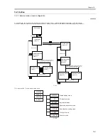
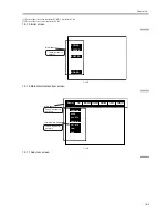
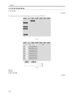
The initial screen (see below) now appears.
F-16-3
16.1.3 Exiting service modes
0009-5961
When the reset key is pressed once, the display returns to the service mode initial screen.
When the reset key is pressed twice, the service modes are exited, and the display returns to the user screen (standard screen).
When using the ADJUST, FUNCTION or OPTION service mode, be sure to turn the main power switch ON/OFF after exiting the mode.
16.1.4 Backing Up Service Mode
0009-5975
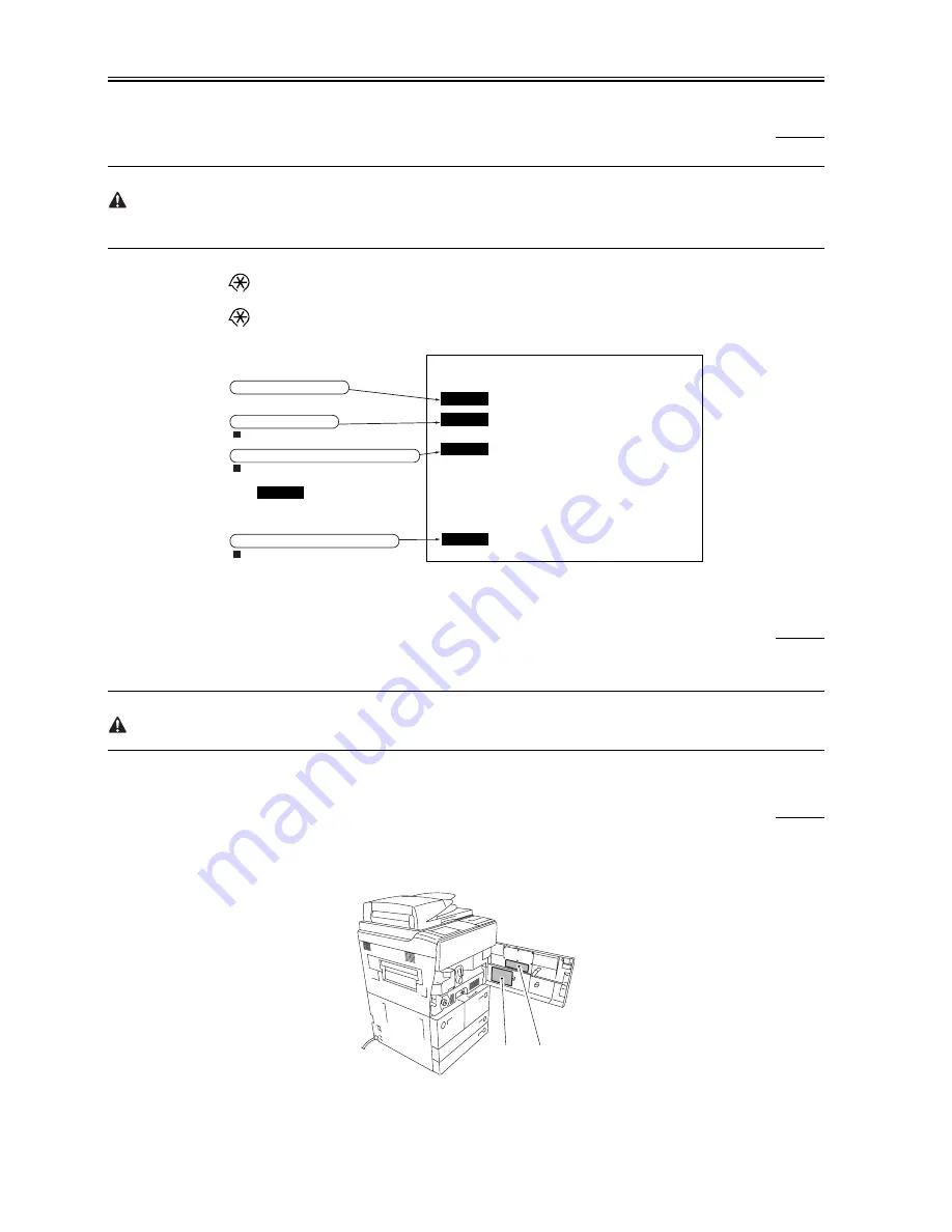
All machines are inspected at time of shipment, and adjustment values are recorded on their service labels. If you have replaced the reader controller PCB
or the DC controller PCB, or if you have initialized the RAM, ADJUST and OPTION will be reset to their default settings. If you have made adjustments
and changed any of the settings, be sure to update the settings recorded on the service label. If specific items are missing on the label, use its blank space.
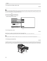
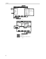
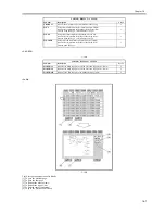
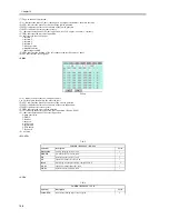
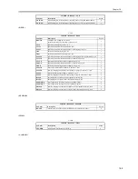
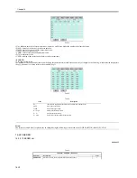
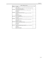
F-16-4
COPIER
FEEDER
SORTER
SORTER
ADF service modes
Displayed only when the ADF is attached.
Displayed only when the finisher is attached.
BOARD
Option board service modes
Displayed only when an option board is
attached.
Copier service modes
Sorter/finisher service modes
(There are no modes for the sorter,
so isn’t displayed even
when the sorter is attached.)
[1]
[2]
Summary of Contents for iR5570 Series
Page 1: ...Mar 29 2005 Service Manual iR6570 5570 Series ...
Page 2: ......
Page 6: ......
Page 26: ...Contents ...
Page 27: ...Chapter 1 Introduction ...
Page 28: ......
Page 30: ......
Page 55: ...Chapter 2 Installation ...
Page 56: ......
Page 58: ...Contents 2 9 3 Mounting the Cassette Heater 2 34 ...
Page 98: ......
Page 99: ...Chapter 3 Basic Operation ...
Page 100: ......
Page 102: ......
Page 110: ......
Page 111: ...Chapter 4 Main Controller ...
Page 112: ......
Page 114: ......
Page 135: ...Chapter 5 Original Exposure System ...
Page 136: ......
Page 181: ...Chapter 6 Laser Exposure ...
Page 182: ......
Page 184: ......
Page 192: ......
Page 193: ...Chapter 7 Image Formation ...
Page 194: ......
Page 198: ......
Page 259: ...Chapter 8 Pickup Feeding System ...
Page 260: ......
Page 350: ......
Page 351: ...Chapter 9 Fixing System ...
Page 352: ......
Page 401: ...Chapter 10 External and Controls ...
Page 402: ......
Page 406: ......
Page 448: ......
Page 449: ...Chapter 11 MEAP ...
Page 450: ......
Page 452: ......
Page 455: ...Chapter 12 Maintenance and Inspection ...
Page 456: ......
Page 458: ......
Page 468: ......
Page 469: ...Chapter 13 Standards and Adjustments ...
Page 470: ......
Page 505: ...Chapter 14 Correcting Faulty Images ...
Page 506: ......
Page 508: ......
Page 537: ...Chapter 15 Self Diagnosis ...
Page 538: ......
Page 540: ......
Page 565: ...Chapter 16 Service Mode ...
Page 566: ......
Page 568: ......
Page 633: ...Chapter 17 Upgrading ...
Page 634: ......
Page 636: ......
Page 641: ...Chapter 17 17 5 F 17 4 HDD Boot ROM Flash ROM System Software ...
Page 646: ...Chapter 17 17 10 F 17 11 8 Click START F 17 12 ...
Page 675: ...Chapter 17 17 39 F 17 59 2 Select the data to download F 17 60 3 Click Start ...
Page 677: ...Chapter 18 Service Tools ...
Page 678: ......
Page 680: ......
Page 683: ...Mar 29 2005 ...
Page 684: ......

