


Part 1: Facsimile
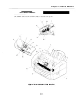
Names and
of parts
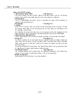
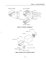
1. Home Position Sensor (HPS)
See Page 2-13.
This sensor detects the home position edge and carriage position. Also, at the capping
position, the on/off of purge sensor flag during the pump operation is detected.
2.
Carriage Motor
This is a stepping/pulse type motor, which is controlled with pulse width modulation. It
moves the carriage by belt drive.
3.
Cartridge
See Page 2-16.
4. Carriage
Driven by the carriage motor, the carriage moves horizontally across the paper. Through
the carriage ribbon cable, the printing signals from the logic board are transmitted to the
cartridge in the carriage.
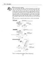
By controlling the purge unit’s slide lock pin, the carriage controls the engagement of the
paper feed motor’s drive power between the paper feed/purge unit and the sheet
feeder.
5. Paper thickness adjustment lever
Adjust the gap between the print head and paper according to the thickness of the paper.
6.
Purge
See Page 2-13.
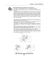
In order to maintain the BJ cartridge’s high print quality, the BJ cartridge’s nozzles and
spray orifices are cleaned by a wiper and pump. When in standby mode, the BJ cartridge’s
spray orifice section is covered by a rubber cap to prevent the nozzles from drying out and
ink from leaking.
The purge unit controls the swing gear. This gear switches power from
paper feed motor
for separation of the paper, paper feed and nozzle cleaning.
7.
Ink Detection Sensor
See Page 2-16.
Ink is ejected directly over the optical axis of a pass-type photosensor, which detects the
change in light intensity to determine whether or not ink is being ejected.
6.
Waste ink absorbers
Absorb waste ink from cleaning or ink empty detection.
2-12
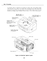
Summary of Contents for C5000 - MultiPASS Color Inkjet Printer
Page 1: ...MultiPASS C5000 SERVICE MANUAL Canon ...
Page 5: ...REVISION I CONTENT 0 I Original ...
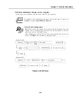
Page 26: ...Chapter 7 General Description 3 1 External View Front View Figure 1 3 External View 1 l 11 ...
Page 27: ...Part 1 Facsimile Rear View Inside the Printer Cover Figure 1 4 External View 2 1 12 ...
Page 28: ...Part 7 Facsimile 3 2 Operation Panel The Operation Panel Document feed lever 0 0 0 0 1 14 ...
Page 34: ...Part 1 Facsimile ...
Page 36: ...Part 7 Facsimile r w Units mm r 0 4 0 0 Figure l 13 Dimensions l 22 ...
Page 65: ...Chapter 1 General Description Waste Ink absorber Figure 1 23 Waste Ink Absorber 1 51 ...
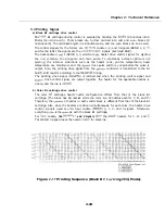
Page 92: ...Part 7 Facsimile Figure 2 18 Printing Signals HQ Mode 2 24 ...
Page 93: ...Chapter 2 Technical Refereno 6 1 Component Block Diagram Figure 2 19 Block Diagram 2 25 ...
Page 150: ...Part 1 Facsimile Figure 3 28 Print Pattern Sample 3 48 ...
Page 184: ...Part 1 Facsimile U Vertical alignment Correction l l l l 3 7 ...