


Chapter 3: Maintenance Service
5.1
Hardware Switches
There is no service hardware switch on the Circuit board.
5.2 Service Data Setting
Service
data can be checked and changed with items on display menus. The default values of
the
available in this fax machine are shown in
Chapter, 5.2.3 Service
data setting
in this manual. The
given in the previous product-specific
manual are explained in the G3 Facsimile
Data Handbook.
The new switches for this
model are described in
this
Service data setting.
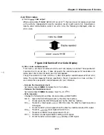
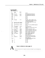
5.2.1 Service data overview
The service data menu items
divided into the following nine blocks
SSSW (Service
Switch settings)
These setting items are for basic fax service functions such as error management, echo
countermeasures, and communication trouble countermeasures.
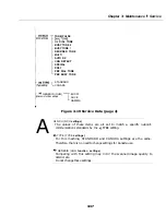
MENU (MENU switch settings)
These setting items are for functions required during installation, such as NL
and transmission levels.
NUMERIC
(NUMERIC parameter settings)
These setting items are for inputting numeric parameters such as the various conditions
for the FAX/TEL switching function.
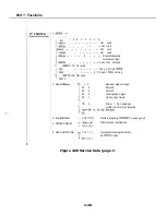
NCU (NCU settings)
These setting items are for telephone network control functions such as the selection
signal transmission conditions and the detection conditions, for the control signals
from the exchange.
TYPE (TYPE setting)
The type setting makes the service data conform to specific country
standards. There is only one setting item in this block.
GENESIS (UHQ
setting)
These setting items are for scanned image processing such as
enhancement and
error diffusion processing.
PRINTER (PRINTER function settings)
These setting items are for basic printer
such as
reception picture
reduction conditions. Also
is an
resetting the printer section without
switching the power off-on.
3-31
Summary of Contents for C5000 - MultiPASS Color Inkjet Printer
Page 1: ...MultiPASS C5000 SERVICE MANUAL Canon ...
Page 5: ...REVISION I CONTENT 0 I Original ...
Page 26: ...Chapter 7 General Description 3 1 External View Front View Figure 1 3 External View 1 l 11 ...
Page 27: ...Part 1 Facsimile Rear View Inside the Printer Cover Figure 1 4 External View 2 1 12 ...
Page 28: ...Part 7 Facsimile 3 2 Operation Panel The Operation Panel Document feed lever 0 0 0 0 1 14 ...
Page 34: ...Part 1 Facsimile ...
Page 36: ...Part 7 Facsimile r w Units mm r 0 4 0 0 Figure l 13 Dimensions l 22 ...
Page 65: ...Chapter 1 General Description Waste Ink absorber Figure 1 23 Waste Ink Absorber 1 51 ...
Page 92: ...Part 7 Facsimile Figure 2 18 Printing Signals HQ Mode 2 24 ...
Page 93: ...Chapter 2 Technical Refereno 6 1 Component Block Diagram Figure 2 19 Block Diagram 2 25 ...
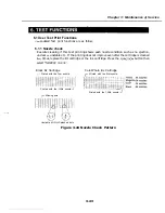
Page 150: ...Part 1 Facsimile Figure 3 28 Print Pattern Sample 3 48 ...
Page 184: ...Part 1 Facsimile U Vertical alignment Correction l l l l 3 7 ...