


Chapter 3: Maintenance Service
NUMERIC
(Numeric parameter 1
0
10 (10%)
15 (15 lines)
12 (12 times)
35:
0
36:
0
37:
0
0
6 (6 digits)
(l-99)
(2-99)
(l-99)
(i-20)
5500 (55 seconds) (O-9999)
11:
3500 (35 seconds) (O-9999)
12:
0
13:
1300 seconds) (O-9999)
14:
0
(O-999)
16:
4 (4 seconds)
(O-9)
100 (1000
(O-999)
(O-999)
19:
200 (4000 ms)
(O-999)
(1000
(O-999)
0 (Oms)
(O-999)
200 (4000
(O-999)
7
(O-9)
2 4 : 20
(O-20)
25:
60 (600 ms)
(O-999)
7
(O-9)
27:
0
0
29:
0
30:
20
Not used
RTN signal transmission condition (1)
RTN signal transmission condition (2)
RTN signal transmission condition (3)
Not used
Not used
Not used
Not used
The number digits in telephone number
compared against TSI signal to be matched
for restricted receiving function
Line connection detection time (TO timer)
Timer (Rx)
Not used
Maximum time to receive
image data
Not used
Hooking detection time
Pseudo RBT transmission from CML on time
until start
Pseudo RBT signal pattern: On time
Pseudo RBT signal pattern: Off time (short)
Pseudo RBT signal pattern: Off time (long)
Pseudo ring pattern: On time setting
Pseudo ring pattern: Off time (short)
Pseudo ring pattern: Off time (long)
switching function
signal detection level
Pseudo-RBT signal transmission level
Answering machine
signal detection time
Answering machine connection function
no sound detection level
Not used
Not used
Not used
Not used
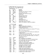
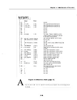
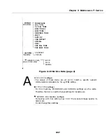
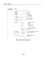
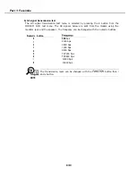
Figure 3-18 Service Data (page 3)
A
N o . 01, 0 5 t o OS, 12, 14, a n d 2 7 t o 3 0 a r e n o t used. D o n o t c h a n g e t h e i r
s e t t i n g s
3-35
Summary of Contents for C5000 - MultiPASS Color Inkjet Printer
Page 1: ...MultiPASS C5000 SERVICE MANUAL Canon ...
Page 5: ...REVISION I CONTENT 0 I Original ...
Page 26: ...Chapter 7 General Description 3 1 External View Front View Figure 1 3 External View 1 l 11 ...
Page 27: ...Part 1 Facsimile Rear View Inside the Printer Cover Figure 1 4 External View 2 1 12 ...
Page 28: ...Part 7 Facsimile 3 2 Operation Panel The Operation Panel Document feed lever 0 0 0 0 1 14 ...
Page 34: ...Part 1 Facsimile ...
Page 36: ...Part 7 Facsimile r w Units mm r 0 4 0 0 Figure l 13 Dimensions l 22 ...
Page 65: ...Chapter 1 General Description Waste Ink absorber Figure 1 23 Waste Ink Absorber 1 51 ...
Page 92: ...Part 7 Facsimile Figure 2 18 Printing Signals HQ Mode 2 24 ...
Page 93: ...Chapter 2 Technical Refereno 6 1 Component Block Diagram Figure 2 19 Block Diagram 2 25 ...
Page 150: ...Part 1 Facsimile Figure 3 28 Print Pattern Sample 3 48 ...
Page 184: ...Part 1 Facsimile U Vertical alignment Correction l l l l 3 7 ...