


Part Facsimile
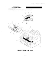
Names and Functions of Parts
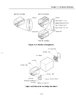
1. Paper Guide
When properly adjusted to the width of the documents, the guide will hold the documents
in
horizontal direction to
them from skewing when fed.
2.
Document Feed Motor
This motor drives all the rollers in the scanner section.
3.
Document Sensor (DS)
This
uses an actuator to
of documents to be scanned, and sends
that information to the SCNT board by
of the gate array in the operation panel unit.
4.
Document Stopper
This stopper is located to the side of the separation rollers, and prevents documents from
entering too far inside the scanning section. This stopper is located here to improve
loading and prevent double feeding or non-feeding due to defective loading of
documents.
5.
Separation Guide
Separates the documents to prevent double-feeding.
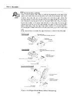
6.
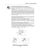
Document Feed Lever
See next page.
This
switches between automatic document feed and manual document feed. Damage
to the document caused by the separation
can be minimized by switching to the
manual document feed position
sending single sheets such as thick-stock paper or
photographs.
7.
Separation Roller
This roller uses differences in the
of friction of the separation guide, document
and separation roller to separate each of the
in a multiple-page document.
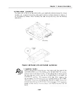
6.
Upper Document Feed Roller
See next page.
When the separation roller starts to rotate, the
document
roller raises the
document stopper so that documents can be
9.
Document Edge Sensor (DES)
Using actuator, the DES detects
of a document
before it reaches
Document Feed Roller
This roller feeds documents to the color contact
they are separated by the
separation roller.
White Sheet
This white sheet is used as a whiteness reference
pre-scanning documents.
12. Color contact Sensor
See page 2-34
The color contact sensor scans the image data from
document,
it to serial
and transmits it to the SCNT board as
signals. The color contact
scanning resolution of
outputs
and
Blue
13. Upper Document Eject Roller
Holds the document
the
end
it.
14.
Document Eject Roller
This
cjrcts
document
15. Static Eliminator Brush
2-4
Summary of Contents for C5000 - MultiPASS Color Inkjet Printer
Page 1: ...MultiPASS C5000 SERVICE MANUAL Canon ...
Page 5: ...REVISION I CONTENT 0 I Original ...
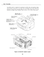
Page 26: ...Chapter 7 General Description 3 1 External View Front View Figure 1 3 External View 1 l 11 ...
Page 27: ...Part 1 Facsimile Rear View Inside the Printer Cover Figure 1 4 External View 2 1 12 ...
Page 28: ...Part 7 Facsimile 3 2 Operation Panel The Operation Panel Document feed lever 0 0 0 0 1 14 ...
Page 34: ...Part 1 Facsimile ...
Page 36: ...Part 7 Facsimile r w Units mm r 0 4 0 0 Figure l 13 Dimensions l 22 ...
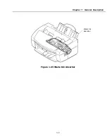
Page 65: ...Chapter 1 General Description Waste Ink absorber Figure 1 23 Waste Ink Absorber 1 51 ...
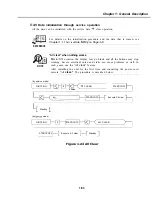
Page 92: ...Part 7 Facsimile Figure 2 18 Printing Signals HQ Mode 2 24 ...
Page 93: ...Chapter 2 Technical Refereno 6 1 Component Block Diagram Figure 2 19 Block Diagram 2 25 ...
Page 150: ...Part 1 Facsimile Figure 3 28 Print Pattern Sample 3 48 ...
Page 184: ...Part 1 Facsimile U Vertical alignment Correction l l l l 3 7 ...